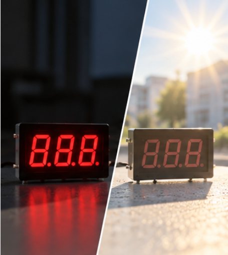
BJT vs MOSFET 7 Segment Display Driver Choice for Multiplexed Designs

Quick Answer: The Digit Current Decides Most of It
A bipolar device needs a continuous base current to stay on, and that current is a fixed fraction of what it is switching. A MOSFET needs a gate charge rather than a gate current, so its drive requirement falls as the device improves, and what remains is a conduction loss set by the on-resistance.
At low digit currents the base drive is trivially available and the BJT is usually the simpler answer. As the digit current rises, the base current becomes a real load on the controller and the saturation voltage becomes a real loss, and the balance moves toward the MOSFET.
Everything else follows from where the device sits in the circuit, which is why the switching position is settled before the device is chosen.
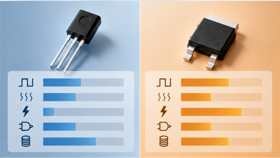
The Two Switching Positions Are Not Symmetric
A multiplexed numeric panel shares one set of segment lines across several digits and selects one digit at a time. That arrangement creates two switching positions: one that sinks or sources the summed digit current, and one that carries a single segment current while its digit is selected.
The digit position is the harder job, because it carries the sum of every lit segment in that digit and it does so only during the digit's slot. The segment position carries a fraction of that current but may be replicated many times across the panel, so its cost is driven by part count as much as by performance.
Which side of the panel each device sits on also depends on the display polarity, because common anode and common cathode parts move the source and sink roles. That distinction changes the control logic and the drive requirement together, and it is set out in our explanation of common anode and common cathode switching logic.
The Comparison Table
The table below sets the two device families against the constraints a multiplexed panel actually imposes, at the same digit current.
| Criterion | Bipolar junction transistor | MOSFET |
|---|---|---|
| Turn-on requirement | Continuous base current, proportional to the switched current | Gate charge only, effectively no steady gate current |
| Conduction behaviour | Fairly constant saturation voltage once driven properly | Resistance that rises with junction temperature |
| Loss at low digit current | Small in absolute terms and easy to predict | Very small, sometimes negligible |
| Loss at high digit current | Saturation voltage multiplies the loss and the base drive load | Loss stays low if the device is correctly selected for the current |
| Switching behaviour | Charge storage delays turn-off unless base drive is designed for it | Gate drive shapes the transition directly |
| Drive logic fit | A resistor from a logic output is often sufficient | Needs enough gate voltage to reach the intended on-resistance |
Two rows carry more weight than they appear to. The conduction row is where a device selected at room temperature can disappoint in a warm enclosure, because saturation voltage is comparatively stable while on-resistance is not. The switching row matters because a digit that does not turn off cleanly can be faintly visible during its neighbour's slot, which is a visible defect rather than a measurable inefficiency.
Choosing in Four Steps
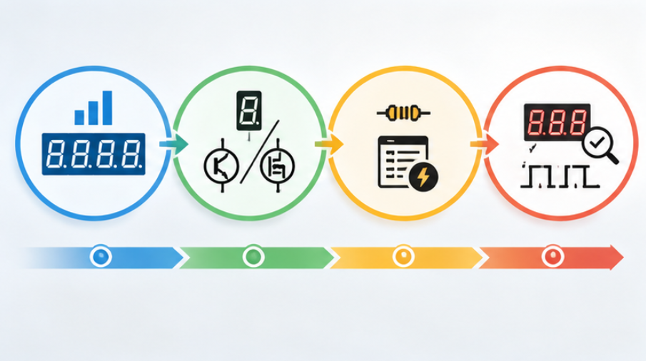
- Fix the digit current. Add the lit segments in the worst-case digit, apply the peak-to-average ratio that the scan imposes, and treat the result as the number every later decision is checked against. The relationship between the two ratings is covered in our comparison of peak against continuous current ratings.
- Decide the switching side. Establish whether the device carries the whole digit or a single segment, and which supply rail it references.
- Size the drive and the loss. For a BJT, budget the base current and confirm the logic output can supply it at the temperature inside the enclosure. For a MOSFET, confirm the gate voltage is high enough for the on-resistance that was assumed.
- Check switching and logic compatibility. Verify turn-off behaviour and confirm the control polarity fits the panel, then compare with the drive-level expectations of a dedicated driver IC if one is still a candidate, as described in our guide to driver IC selection and current setting.
Where the answer lands close, the tie is usually broken by what is already on the board. Reusing a device family that the project already stocks reduces qualification work and part-count risk, and the topology for larger digits is discussed in our guide to the drive topology for a large digit.
Where the Decision Goes Wrong
The most common error is to compare the two devices at the bench current rather than at the worst-case digit current. A drive stage that is comfortable at one output digit becomes marginal when the firmware displays a row of eights, because that condition lights every segment and the digit current reaches its maximum.
The second error is to check the device while it is switching and stop there. Conduction loss is a steady-state effect inside the enclosure, and the enclosure temperature is usually higher than the bench, so the device has to be evaluated at the temperature the product will hold rather than at the temperature it was tested at.
The third is a control-logic mismatch. A device that requires an inverted control signal compared with the one the firmware was written for will invert the display, and this is easy to miss on a schematic review and obvious on a first prototype. Confirming the polarity of the scan timing, as described in our explanation of scan timing in a multiplexed panel, prevents a round of rework.
Validating the Choice Before Production
Validation should reproduce the conditions that the decision assumed, which means the real firmware, the real digit content and the real enclosure.
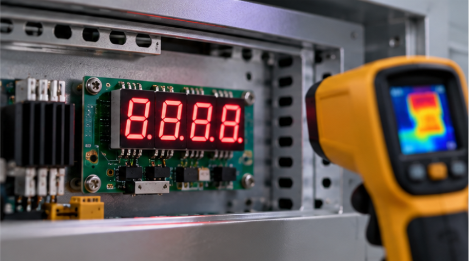
Display the worst-case pattern, meaning the digit content that draws the most current, and measure the device case temperature at thermal steady state rather than immediately after start-up. Then confirm that the digit does not remain faintly lit during another digit's slot, since a small residual conduction is easy to miss on a bench and noticeable on a finished panel.
Finally, repeat the measurement at the extremes of the supply range, because the base drive available from a logic output falls with the supply while the gate voltage available to a MOSFET may fall below the value used for the loss calculation. Both effects are largest exactly where the panel is most likely to be judged, at the low end of a battery-powered supply or at the cold end of a specification.
Frequently Asked Questions
How do BJT vs MOSFET 7 segment display driver options compare for OEM designs?
A BJT needs continuous base current and has a fairly constant saturation voltage, while a MOSFET needs only gate charge and has a temperature-dependent on-resistance. The comparison changes with the digit current, which is why the current budget comes first.
Which BJT vs MOSFET 7 segment display driver choice fits an industrial application?
Industrial panels usually favour whichever device stays within its thermal budget at the worst-case digit current inside the enclosure. Where the digit current is high or the enclosure is warm, the MOSFET often holds its loss better once the gate drive is confirmed.
What trade-offs matter when comparing BJT vs MOSFET 7 segment display driver?
Drive current, conduction loss at temperature, turn-off behaviour and logic-level compatibility are the four that decide the outcome. Cost and part availability act as tie-breakers once those four are satisfied.
How should engineers validate a BJT vs MOSFET 7 segment display driver decision?
Display the pattern that draws the most current and measure the device temperature at steady state inside the real enclosure. Repeat across the supply range and confirm that no digit remains faintly lit outside its own slot.
Can a logic output drive the switching device directly?
Often yes for the segment position, where the current is small, and less often for the digit position, where the drive current or the gate charge may exceed what the output can supply cleanly. The budget should be checked at the lowest supply voltage the product will see.
Conclusion: Set the Current, Then Compare
The BJT vs MOSFET 7 segment display driver question has a defensible answer as soon as the digit current, the switching position and the enclosure temperature are fixed. Fix those first and the device choice becomes a check rather than a preference.
The same order makes 7 segment LED design, multi-digit LED display design and 7-Segment Drive & Circuit Design work reviewable, because each switching decision is recorded with the current and temperature it was based on. That is what allows a second panel design to reuse the decision instead of repeating the evaluation.
If you are specifying a multiplexed numeric panel and want the digit current, drive position and device options reviewed against the actual layout, send the panel details and the operating conditions through the inquiry page.
7 Segment Display PWM Dimming: Brightness Control Without Color Shift