What Is LED Multiplexing in 7 Segment Displays?

The scanning sequence happens quickly enough that the human eye perceives all digits as being continuously lit. This effect makes multiplexing a practical way to control a multi-digit 7 segment display while reducing the number of microcontroller pins, PCB traces and driver components required.
This method is commonly used in:
-
Digital meters
-
Industrial control panels
-
Timers and counters
-
Test equipment
-
Household appliances
-
Medical devices
-
Power supplies
-
Measurement instruments
Although the basic principle is straightforward, reliable 7 segment display multiplexing depends on several connected design decisions. The scan ratio, duty cycle, refresh rate, current-limiting method and driver switching sequence all influence brightness, flicker and display stability.
For OEM engineers, understanding these factors early can prevent dim output, ghosting and costly PCB revisions later in the project.
Why Multi-Digit 7 Segment Displays Use Multiplexing
A conventional 7 segment digit contains seven LED segments identified as A through G. Many models also include a decimal point, giving the controller up to eight individual LED elements to manage.
If every segment in a four-digit display were controlled independently, the circuit would require a large number of MCU outputs and PCB connections. That approach may work in a simple prototype, but it becomes inefficient in compact or cost-sensitive products.
A multiplexed 7 segment display solves this problem by allowing corresponding segments to share the same control lines.
For example:
-
All A segments share one line.
-
All B segments share one line.
-
All C segments share one line.
-
The same arrangement continues through G and the decimal point.
Each digit then has a separate digit-select connection. The controller places the required pattern on the shared segment lines and activates only the digit that should display that pattern.
A four-digit module may therefore require eight segment lines and four digit-select lines, rather than a separate group of segment lines for every digit.
The main advantages include:
-
Fewer MCU GPIO pins
-
Simpler PCB routing
-
Lower component count
-
Smaller connectors
-
Easier expansion to additional digits
-
Lower system cost
The trade-off is that the display is no longer controlled by simple continuous DC signals. Firmware timing and driver performance become part of the optical design.
How a Multiplexed 7 Segment Display Is Wired
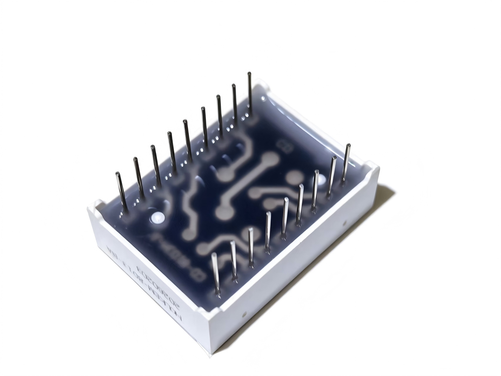
A multi-digit 7 segment display normally contains two groups of connections: shared segment lines and individual digit-select lines.
The shared lines determine which segments should illuminate. The digit-select lines determine where that pattern appears.
Suppose the controller needs to show the number 2. It activates segments A, B, G, E and D. If digit two is selected at that moment, the number 2 appears in the second position. The same segment pattern can later be applied to another position by changing the active digit-select line.
This shared structure is the basis of LED multiplexing in 7 segment displays.
However, engineers should not assume that displays with the same external dimensions or pin count have identical internal wiring. Before designing the PCB, confirm:
-
Pin configuration
-
Common anode or common cathode type
-
Segment polarity
-
Decimal-point location
-
Forward voltage
-
Recommended current
-
Internal digit arrangement
A pinout mismatch discovered after the PCB is manufactured can be far more expensive than confirming the display drawing during the sample stage.
Common Anode vs Common Cathode Multiplexing
The multiplexing circuit must match the electrical configuration of the display.
In a common cathode display, the cathodes of the LED segments within each digit are connected together. The controller selects a digit by pulling its common cathode toward ground while driving the required segment lines high.
In a common anode display, the segment anodes share a positive connection. The selected digit is supplied from the positive rail, while the required segment lines are driven low.
The two configurations therefore use opposite control logic.
They may also require different transistor arrangements. Common cathode designs often use low-side switching for digit selection, while common anode designs may require high-side switching. The exact topology depends on current requirements, supply voltage and the capabilities of the selected driver.
For an OEM project, common type should be confirmed before firmware and PCB development begin. Two displays may look identical but require different logic levels and external driver circuits.
How to Multiplex 7 Segment Displays Step by Step
The easiest way to understand how to multiplex 7 segment displays is to follow one complete scanning cycle.
Assume a four-digit display needs to show “1234.” The controller performs the following sequence:
-
Turn off all digits.
-
Output the segment pattern for the number 1.
-
Activate the first digit.
-
Keep it active for a short period.
-
Turn the first digit off.
-
Output the segment pattern for the number 2.
-
Activate the second digit.
-
Repeat the process for the third and fourth digits.
-
Return to the first digit and begin the cycle again.
At any instant, only one digit may be active. Because the sequence repeats rapidly, the user sees a stable four-digit number rather than a series of flashing individual digits.
The order of operations matters. A reliable sequence usually follows a break-before-make approach:
-
Disable the current digit.
-
Update the segment data.
-
Allow a short blanking interval if required.
-
Enable the next digit.
Changing segment data while the previous digit is still active can briefly illuminate the wrong segments. This is one of the most common causes of 7 segment display ghosting.
Understanding the 7 Segment Display Scan Ratio
The 7 segment display scan ratio describes how many digits share one complete scanning cycle.
Common examples include:
-
Two digits: 1:2 scan
-
Three digits: 1:3 scan
-
Four digits: 1:4 scan
-
Six digits: 1:6 scan
-
Eight digits: 1:8 scan
In a four-digit display using a 1:4 scan ratio, each digit is theoretically active for one quarter of the total scanning cycle.
As the number of digits increases, the available active time for each digit becomes shorter. This matters because LED brightness depends partly on how long each segment is on.
A display that looks bright during a static bench test may appear noticeably dimmer when operated at a high scan ratio. That difference is often overlooked when engineers evaluate a sample using continuous DC power instead of the final multiplexing circuit.
The display supplier should therefore know the intended scan ratio before recommending an LED chip, brightness level or electrical specification.
How 7 Segment Display Duty Cycle Affects Brightness
The 7 segment display duty cycle is the percentage of each complete cycle during which a digit remains active.
In an ideal system:
| Number of digits | Scan ratio | Theoretical duty cycle per digit |
|---|---|---|
| 2 | 1:2 | 50% |
| 3 | 1:3 | 33.3% |
| 4 | 1:4 | 25% |
| 6 | 1:6 | 16.7% |
| 8 | 1:8 | 12.5% |
The real duty cycle may be slightly lower because of blanking intervals, switching delays and firmware overhead.
When duty cycle decreases, the average current through each LED also decreases. Designers sometimes compensate by increasing the pulse current during the short active period.
That approach must be handled carefully. The peak current cannot be selected from the continuous-current rating alone. Engineers must check the display datasheet for:
-
Maximum pulse current
-
Permitted pulse width
-
Allowed duty cycle
-
Junction temperature limits
-
Forward-voltage behavior
-
Thermal conditions
Applying excessive peak current may produce a bright prototype in the short term but reduce LED life or create uneven output in production.
Brightness should always be evaluated under the actual scan ratio and pulse conditions planned for the finished product.

Choosing a Suitable 7 Segment Display Refresh Rate
The 7 segment display refresh rate refers to how often the controller completes a full scan of all digits.
If the full-display refresh rate is too low, users may see flicker. The effect can become more noticeable when the viewer moves their eyes, looks from the side or uses the product in a dim environment.
A display that appears stable to the eye may still show dark bands when recorded by a smartphone, machine-vision camera or security system. This happens when the camera shutter and the display scanning sequence are not synchronized.
The correct refresh rate depends on several factors:
-
Number of digits
-
MCU processing load
-
Timer configuration
-
Required dimming resolution
-
Driver switching speed
-
Camera exposure conditions
-
EMC requirements
-
Target brightness
A higher refresh rate is not automatically better. If switching becomes too fast, the controller may spend a larger proportion of each cycle on blanking and data updates. Slow transistors may also fail to turn fully on or off before the next digit is selected.
In most designs, a timer interrupt provides more stable scanning than a software loop based on long delay functions. The display refresh process should continue at a consistent rate even when the MCU is handling communication, sensing or other application tasks.
What Causes 7 Segment Display Ghosting?
7 segment display ghosting is the appearance of faint or incorrect segments on a digit that should be off or displaying another number.
The problem usually comes from signal overlap during digit switching.
Common causes include:
-
Updating segment data before disabling the previous digit
-
Insufficient blanking time
-
Slow transistor turn-off
-
Driver storage charge
-
Floating control lines
-
Incorrect pull-up or pull-down resistors
-
PCB coupling
-
Firmware timing variation
-
Excessive scanning speed
A short blanking interval between digits often improves the result. However, blanking should not be increased more than necessary because it also reduces the effective duty cycle.
Ghosting should be evaluated using realistic display patterns. Repeating the same number across every digit may hide the problem. A better test is to display patterns with large segment differences, such as “1818” or “1234.”
This makes unwanted carryover from one digit to the next easier to detect.
Why Multiplexed Displays Sometimes Have Uneven Brightness
Uneven brightness can have several causes, and not all of them are related to LED quality.
One common issue is the use of a single resistor on the common digit connection. The current is then shared between all illuminated segments. A digit showing “1” uses only two segments, while a digit showing “8” uses all seven. The current through each segment may therefore change with the displayed number.
Using an individual resistor for each shared segment line generally provides more predictable current control.
Other causes of uneven brightness include:
-
Different digit on-times
-
Voltage drop across digit drivers
-
Unequal PCB resistance
-
Insufficient driver current
-
Poor timer consistency
-
LED wavelength or chip variation
-
Thermal differences across the module
For applications that require tight brightness uniformity, a constant-current driver may offer better results than simple resistor-based control.
MCU Direct Drive vs a 7 Segment Display Driver IC
A small display with low current requirements may be driven directly from MCU GPIO pins. This can reduce component count, but the total current must remain within both the per-pin and package-level limits of the microcontroller.
The digit-select line may carry the combined current of several illuminated segments. Even when each segment current appears acceptable, the total load can exceed what one GPIO pin should handle.
External driver options include:
-
NPN or PNP transistors
-
N-channel or P-channel MOSFETs
-
Darlington transistor arrays
-
Shift registers
-
Dedicated display driver ICs
-
Constant-current LED drivers
A shift register can reduce the number of MCU pins, but it does not automatically solve current-handling or multiplexing-timing requirements.
A dedicated 7 segment display driver IC may provide:
-
Automatic scanning
-
Serial communication
-
Current regulation
-
Brightness control
-
Segment decoding
-
Display blanking
-
Reduced MCU workload
The best choice depends on the number of digits, display size, brightness target, unit cost, available PCB space and production volume.
When Should Engineers Use Multiplexing?
Multiplexing is usually a good choice when a product needs multiple digits and must keep component count or PCB size under control.
It is particularly useful for:
-
Compact control panels
-
Battery-powered devices
-
Digital meters
-
High-volume appliances
-
Embedded products with limited GPIO
-
Products requiring software-controlled brightness
Static drive may still be preferable when:
-
Maximum brightness is critical
-
The display has very few digits
-
Camera compatibility is a major requirement
-
Firmware complexity must remain minimal
-
The application cannot tolerate scan-related artifacts
The decision should be based on the complete system rather than display cost alone.
What to Confirm Before Ordering a Multi-Digit Display
Before requesting a quotation or approving a sample, OEM teams should provide the display manufacturer with clear electrical, optical and mechanical requirements.
Important details include:
-
Number of digits
-
Character height
-
Overall package dimensions
-
Common anode or common cathode
-
Pin configuration
-
Display color and wavelength
-
Target brightness
-
Forward voltage
-
Segment current
-
Intended scan ratio
-
Operating voltage
-
Viewing angle
-
Operating temperature
-
Decimal-point arrangement
-
PCB mounting method
-
Annual order quantity
The intended driving method is especially important. A display selected for static operation may not deliver the same visual result under 1:4, 1:6 or 1:8 scanning.
For custom displays, the manufacturer may also need the PCB drawing, available installation space and required pin orientation.
Testing a Multiplexed 7 Segment Display Sample
A useful sample test should reproduce the real operating conditions of the finished product.
Do not judge the display only by connecting one digit to a DC supply. Instead, test it using:
-
The planned scan ratio
-
Final or equivalent driver components
-
Expected supply voltage
-
Real segment current
-
Intended dimming method
-
Actual viewing distance
-
Minimum and maximum operating temperatures
-
Camera recording, where relevant
Engineers should check:
-
Overall brightness
-
Brightness consistency between digits
-
Flicker
-
Ghosting
-
Driver temperature
-
Segment color consistency
-
Visibility at different viewing angles
-
Performance at low brightness settings
Testing with the real multiplexing method gives a far more accurate picture of production performance.
Conclusion
LED multiplexing in 7 segment displays allows multiple digits to share segment lines while the controller activates each digit in rapid sequence. It reduces MCU pin requirements, simplifies PCB routing and makes multi-digit displays more practical for compact, high-volume products.
The basic scanning process is simple, but good results depend on more than switching digits quickly. Engineers must also consider the 7 segment display scan ratio, duty cycle, refresh rate, peak current, blanking time and driver switching behavior.
A well-designed multiplexed 7 segment display should provide stable brightness, clean digit transitions and no visible flicker under normal operating conditions.
For OEM and ODM projects, it is best to define the driving method before selecting the final display. HOUKEM supplies standard and custom multi-digit 7 segment LED displays for meters, appliances, industrial controls and embedded electronics. Customers can provide their dimensions, common type, pin layout, scan ratio, brightness requirements and expected order volume for sample evaluation and customization support.
FAQs About LED Multiplexing in 7 Segment Displays
What is multiplexing in a 7 segment display?
Multiplexing is a driving method in which multiple digits share the same segment lines. The controller activates each digit for a short period and repeats the sequence fast enough to create the appearance of continuous illumination.
Does multiplexing make a 7 segment display dimmer?
It can. Each digit is active for only part of the scanning cycle, so its average current is lower than under static drive. Brightness depends on scan ratio, duty cycle, LED efficiency and permitted peak current.
What is a 1:4 scan ratio?
A 1:4 scan ratio normally means that four digits share one scanning cycle. Each digit has a theoretical duty cycle of approximately 25%, although blanking and switching time may reduce the actual value.
How can engineers reduce ghosting between digits?
Turn off the current digit before changing the segment data, add a short blanking interval and confirm that the transistor or driver can switch off quickly enough.
Is a driver IC necessary for a multiplexed display?
Not always. A small, low-current display may be driven by an MCU and external transistors. A dedicated driver IC becomes more useful when the project requires more digits, higher current, stable brightness or lower MCU workload.
How to Choose a COB LED Module for OEM Lighting Projects
How to Select a Numeric LED Display for an OEM Product