LED Pulse Current vs Continuous Current: How to Read Both Ratings

What the Two Ratings Describe
The continuous rating describes steady-state operation, where the die carries a constant current long enough for its temperature to settle. The pulse rating describes a short, repetitive event, and it is always quoted with a pulse width and a duty condition, because the die has less time to heat during a short pulse than during a steady one. Reading those limits correctly is a prerequisite: reading LED specifications covers how the rating tables are structured, and the difference between an operating point and an absolute maximum is set out in forward current versus rated current. This article builds on those two foundations and deals with the second question: once you know which rating is which, how do you choose an operating point and prove it will hold?

Which Parameters Matter Most for LED Pulse Current vs Continuous Current
Which parameters matter most for LED pulse current vs continuous current? Pulse width and duty cycle come first, because they determine how much heating time the die receives and how much of the brightness benefit survives. Repetition rate matters next, since a fast repetition with short gaps behaves differently from a slow one with long gaps even at the same average current. The thermal path of the package and board decides how quickly heat leaves, and the ambient or case temperature sets the starting point for every calculation. Forward voltage at the elevated peak current is the last input, because the drive circuit has to supply it. The table below summarizes the decision inputs.
| Parameter | Where It Comes From | Effect on the Decision |
|---|---|---|
| Pulse width | Driver timing, application refresh or modulation scheme | Short pulses allow a higher instantaneous current for the same heating |
| Duty cycle | On-time relative to the full period | Sets the average current and therefore the steady-state heat load |
| Repetition rate | Driver frequency and control method | Changes how much the die cools between pulses |
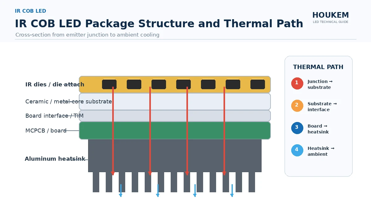
| Thermal path | Package type, board copper, heatsinking | Determines how efficiently the average heat load is removed |
| Ambient or case temperature | Enclosure design and nearby heat sources | Raises the starting temperature and reduces the usable margin |
| Forward voltage at peak | Datasheet curve or measurement | Confirms the driver and series components can supply the pulse |
How Duty Cycle Ties Peak Current to Average Current
The average current is the peak current multiplied by the duty cycle, which is why a pulsed design can drive a die harder for a moment while keeping the long-term heat load modest. The simplification is useful but incomplete. Heat does not average perfectly, because the junction responds on a fast time constant and the package responds on a slower one, so a very short pulse at a very high current can still create a local temperature excursion that the average figure hides. For practical LED electrical design, the safe method is to size the steady-state thermal path against the average current and then check the peak against the pulse rating and the switching capability of the driver. Where a series resistor is used to set the current, its value and power rating must be checked against the peak rather than the average, since that is the condition the resistor actually sees; calculating a current limiting resistor walks through that check.

How Does LED Pulse Current vs Continuous Current Affect LED Performance
How does LED pulse current vs continuous current affect LED performance? It changes the balance between output, efficiency and heat. Optical output rises with current but not perfectly linearly, and efficiency tends to fall as current density climbs, so a pulsed drive can deliver more instantaneous light without proportionally more average heat. The cost is a hotter die at each pulse, which pushes wavelength and forward voltage around and shortens the margin against the absolute maximum. This is why LED Electrical Design & Derating treats the two ratings as a pair: the continuous figure protects the package over time, and the pulse figure protects the die during each event, and a design that respects only one of them is not yet safe. LED thermal design and current design are the same conversation at this point.
How Should Engineers Validate LED Pulse Current vs Continuous Current Before Production
How to evaluate LED pulse current vs continuous current for an OEM design is a bench exercise with three measurements. First, measure the actual waveform with a current probe rather than trusting the nominal driver setting, because rise time, overshoot and ringing all consume margin. Second, measure case temperature at steady state under the real duty cycle in the real enclosure, then convert it to junction temperature with the package thermal resistance; thermal resistance explained and calculating junction temperature provide the two halves of that step. Third, repeat the measurements at the temperature extremes the product will see, since a pulse rating that passes at room temperature may not pass in a warm enclosure. That is how should engineers validate LED pulse current vs continuous current before production: as a recorded set of waveform and temperature checks with margins stated, not as a single reading taken on a cold bench.
Frequently Asked Questions
Can I run an LED continuously at its peak current rating?
No, the peak rating applies only under the pulse width and duty condition printed beside it. Running that current continuously changes the thermal condition and leaves the safe operating area.
Does a 50 percent duty cycle mean half the brightness?
Not exactly, because the die continues to emit during each pulse and the eye integrates the pulses. The average optical output tends to follow the average current, with additional losses at high current density.
Why does the datasheet quote a pulse width as well as a duty cycle?
Both are needed to describe the heating condition, because a short pulse in a long period and a long pulse in a short period are not equivalent. Using the peak value without that pair is unsafe.
Is pulsed drive a good way to avoid heat problems?
It can raise instantaneous output without raising average current, which helps when the limitation is average heat. It does not remove the need for a proper thermal path, because the peak event still heats the die.
What should I check first when a pulsed design runs hot?
Check the measured average current before changing the thermal design, since duty cycle errors are a common cause. Then verify the case temperature and the junction estimate against the derating curve.

Bringing Both Ratings Together
Continuous current and pulse current answer different questions, and a durable design answers both: average current for the steady thermal load, peak current and its timing for the electrical and thermal transient. When those numbers are measured, derated and recorded together with the enclosure temperature, LED pulse current vs continuous current stops being an ambiguous datasheet pair and becomes a specification you can defend. If you are integrating LEDs or displays into a new OEM product and want the current ratings and thermal margins confirmed against the actual component data, send your design requirements to HOUKEM and the engineering team will support the review.
LED Current Limiting Resistor Calculation: A Practical Design Guide