SMD LED Anode and Cathode: How to Identify Polarity Correctly
Why SMD Polarity Is Easy to Get Wrong
Unlike a through-hole LED, an SMD part has no long lead to act as a reminder of orientation. Orientation is carried by the footprint drawing, by a small package feature and by the pin numbering on the datasheet, and those three pieces of information are often read at different times by different people. When a footprint library is copied from a previous project, the polarity convention can be inherited from a different part family without anyone noticing.
The result is that led anode cathode identification becomes a verification task rather than a reading task, and smd led anode and cathode identification is best handled as a check rather than an assumption. Treating it as a check removes the failure mode, because a check produces a result that can be recorded and repeated.
Start With the Datasheet and Footprint Drawing
The authoritative source is the manufacturer drawing for the exact part number, because polarity orientation is defined by the supplier rather than by a universal convention. The drawing shows which pad is which and how the package sits relative to those pads. The datasheet pinout for the part should be read together with the footprint, because the smd led datasheet pinout carries the pad assignment while the footprint carries the geometry. A footprint that matches a drawing in outline can still mirror that assignment, which is why the two have to be compared rather than assumed to agree.
Reading those documents correctly depends on being able to follow the parameter tables and drawings consistently, which is the same skill described in reading LED specifications. For display parts there is an additional layer of pin numbering to follow, as set out in reading an LED display datasheet.
Package Polarity Marks and Their Limits
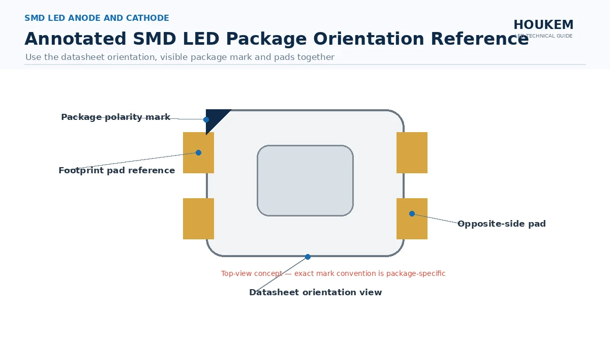
Smd led polarity marking on a package is a cross-check, not a definition. Common conventions include a chamfer or cut corner, a notch on one edge, a small dot, or an asymmetric pad shape, and different package families use different ones. Because no single mark is universal, a mark should never be the only evidence used to decide orientation on a production build.
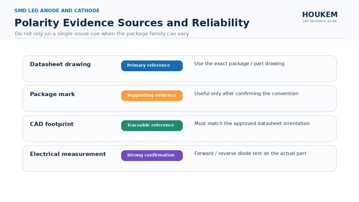
| Evidence source | What it gives you | Reliability for production |
|---|---|---|
| Datasheet or drawing | Definitive pad and orientation assignment for the part number | Authoritative, provided the correct revision is used |
| Package polarity mark | A visible orientation cue on the physical part | Useful cross-check, not sufficient alone |
| Footprint in the CAD library | The pad geometry the assembly machine will use | Must be verified against the drawing, not assumed |
| Forward-voltage measurement | Direct electrical confirmation on the actual part | Strongest confirmation for the physical device |
Electrical Confirmation on the Actual Part
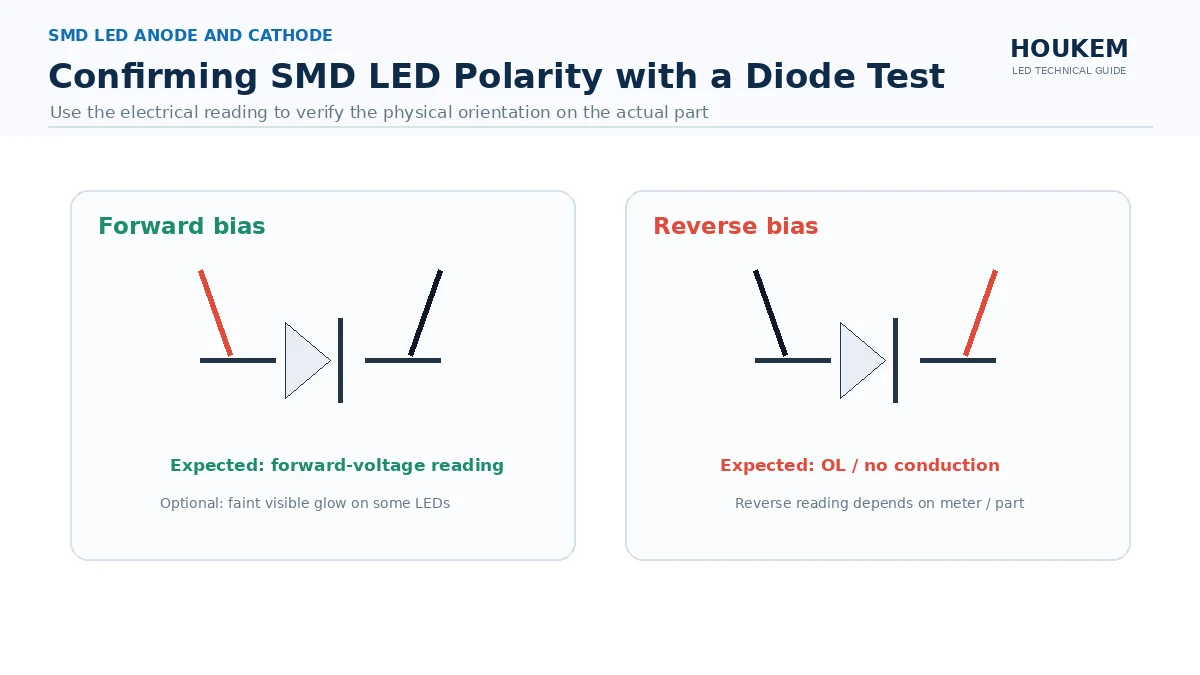
The most trustworthy check happens on the deliverable. How to identify led anode and cathode with a multimeter is straightforward: in diode-test mode the LED conducts in the forward direction and shows a voltage drop, or emits light in a visible part, while the reverse direction does not conduct. Because the measurement is made on the physical device, it also catches a part that has been marked or packed inconsistently.
For infrared and ultraviolet parts the visible-light cue is absent, so the measurement has to rely on the electrical reading rather than on a visible glow. That is one reason polarity verification for non-visible emitters belongs in the inspection instruction rather than in an operator judgement call.
What the Inspection Instruction Should Say
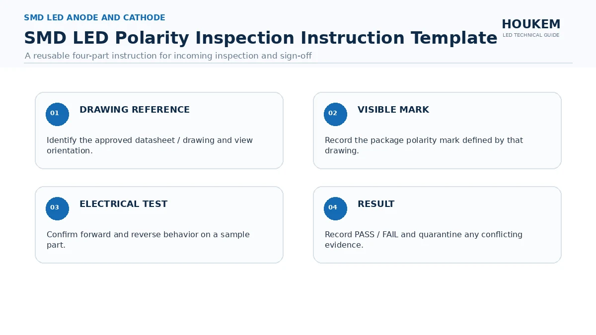
An inspection instruction that produces a decision has four parts:
- The drawing or datasheet reference that defines orientation for the exact part number.
- The physical mark to look for, described in terms that match the actual package.
- The electrical test that confirms orientation on the sampled part.
- The result that counts as a failure, stated so the check returns pass or fail rather than an observation.
How to tell which side is anode on an smd led then becomes a repeatable procedure instead of a judgement about a photograph. The same three-source logic applies when polarity sits inside a larger circuit decision, such as the architecture choice between common anode and common cathode drive, which is examined in common anode versus common cathode architecture.
For multi-digit displays, orientation and pin function are read together, because a correct orientation with a wrong digit mapping produces a display that lights the wrong segments. Reviewing the SMD 7 segment display range alongside the applicable datasheet is the practical way to close that gap before the footprint is signed off.
Frequently Asked Questions
Which side of an SMD LED is the anode?
There is no single answer that applies to every package family, because the polarity orientation is defined by the manufacturer drawing. The reliable rule is to read the orientation from the datasheet drawing for the exact part number and then confirm it on the physical part.
How is the cathode marked on an SMD LED package?
Common conventions include a corner chamfer, a notch, a dot or an asymmetric pad shape, but no single mark is universal. Treat the marking as a cross-check only and never as the sole source for a production decision.
Can a multimeter be used to find LED polarity?
Yes, in diode-test mode a forward-biased LED emits light or shows a voltage drop, while the reverse direction does not. The measurement confirms orientation on the actual part, which is why it is the most trustworthy of the three checks.
Why does reversed polarity damage an LED?
A reversed part sits in the blocking direction, so the circuit either fails to light or forces current through a path the design did not intend. In a multiplexed design a reversed emitter can also disturb the adjacent segments or columns.
What should an inspection instruction say about polarity?
It should name the drawing reference for orientation, the marking to look for and the electrical test that confirms it. It should also state the result that counts as a failure, so the check produces a decision rather than an observation.
How does polarity apply to multi-digit SMD displays?
Multi-digit parts add a digit and segment pinout on top of the polarity question, so orientation and pin function have to be read together. Review the SMD display range and the applicable datasheet before finalising the footprint.
Making Polarity a Check Rather Than an Assumption
Polarity errors persist because they are cheap to prevent and expensive to discover. A drawing reference, a visible mark and one electrical measurement take a few minutes per part family and remove a failure mode that otherwise appears after reflow, when the cost of correction is at its highest.
If you are finalising a footprint for an SMD or multi-digit display part, confirm the pin numbering and orientation against the applicable drawing before releasing the board, and send your package and pinout question so the pinout for your part number can be confirmed.
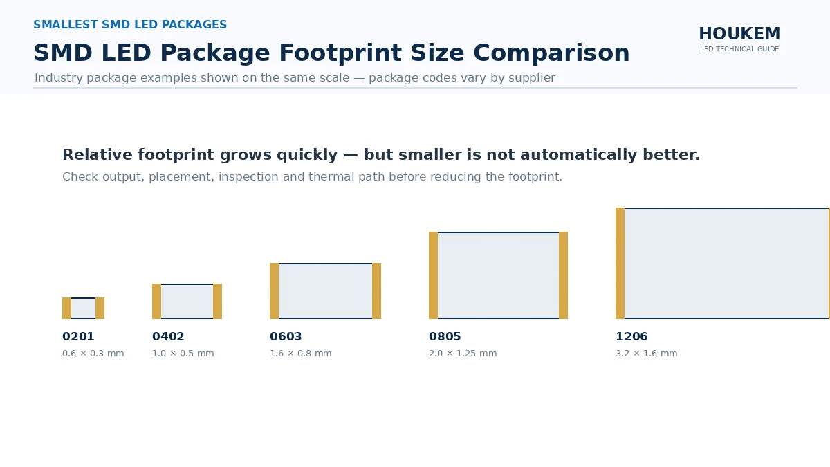
Smallest SMD LED Packages: How Package Size Shapes Your Design
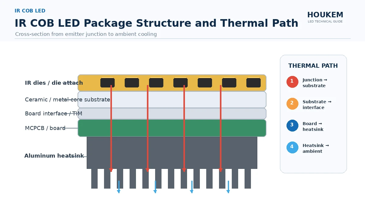
IR COB LED: Why High-Power Infrared Emitters Use Chip-on-Board Packaging