MCPCB vs FR4 LED Thermal Design: Choosing the Right Substrate

What Is the Difference Between MCPCB and FR-4 for LED Boards?
The difference is not the surface copper but what sits underneath it. FR-4 is a glass-reinforced epoxy laminate, so the heat path from the copper pad down through the board is dominated by a resin-rich dielectric. An MCPCB, also called a metal core PCB, replaces that base with aluminium or copper and keeps only a thin thermally conductive dielectric between the copper and the metal.
| Property | FR-4 | MCPCB (metal core) |
|---|---|---|
| Base material | Glass-reinforced epoxy laminate | Aluminium or copper base with a thin dielectric layer |
| Dominant thermal path | Through-plane conduction limited by the laminate dielectric | Through-plane conduction through a thin dielectric into a metal base |
| Spreading in the plane | Modest; relies heavily on copper planes and vias | Strong; the metal base spreads heat laterally on its own |
| Mechanical character | Rigid, light, well established for dense circuitry | Stiffer and heavier; machining and layout rules differ |
| Typical role | Logic, control circuitry, low and moderate power emitters | High-power emitters, arrays and dense multi-die packages |
The practical consequence is that an MCPCB does not remove heat better because its copper is different, but because its dielectric layer and base give heat a much shorter and wider route to the mounting surface. That is why the MCPCB thermal path is dominated by the dielectric thickness rather than by copper weight. Our overview of LED thermal management places that route within the wider junction-to-ambient chain.
Why FR-4 Reaches Its Limit Under High-Power LEDs
FR-4 designs fail thermally for a small number of predictable reasons rather than through a gradual decline.
Heat has to cross the dielectric
In a conventional FR-4 stack-up, the vertical path from the thermal pad to the bottom copper passes through laminate whose thermal conductivity is low compared with metal. Copper spreads heat well in its own plane, but it cannot compensate for a poor through-plane path if the dielectric is the bottleneck. Thermal vias help by giving heat a parallel route through copper barrels, and their effectiveness depends heavily on via count, barrel plating and how closely they are clustered under the pad.
Thermal resistance accumulates along the path
Each layer in the stack-up contributes its own thermal resistance, and the resistances add. The distinction between the junction-to-board and junction-to-ambient paths is what makes a design succeed on the bench and then overheat inside an enclosure, and it is covered in detail in our explainer on thermal resistance parameters. When the sum of internal resistances is already large, no heatsink can repair the design.
When MCPCB Becomes the Practical Choice
When evaluating MCPCB vs FR4 for high power LEDs, the transition point is best defined by power density and by how much thermal budget the rest of the design has already spent.
Power density and array size
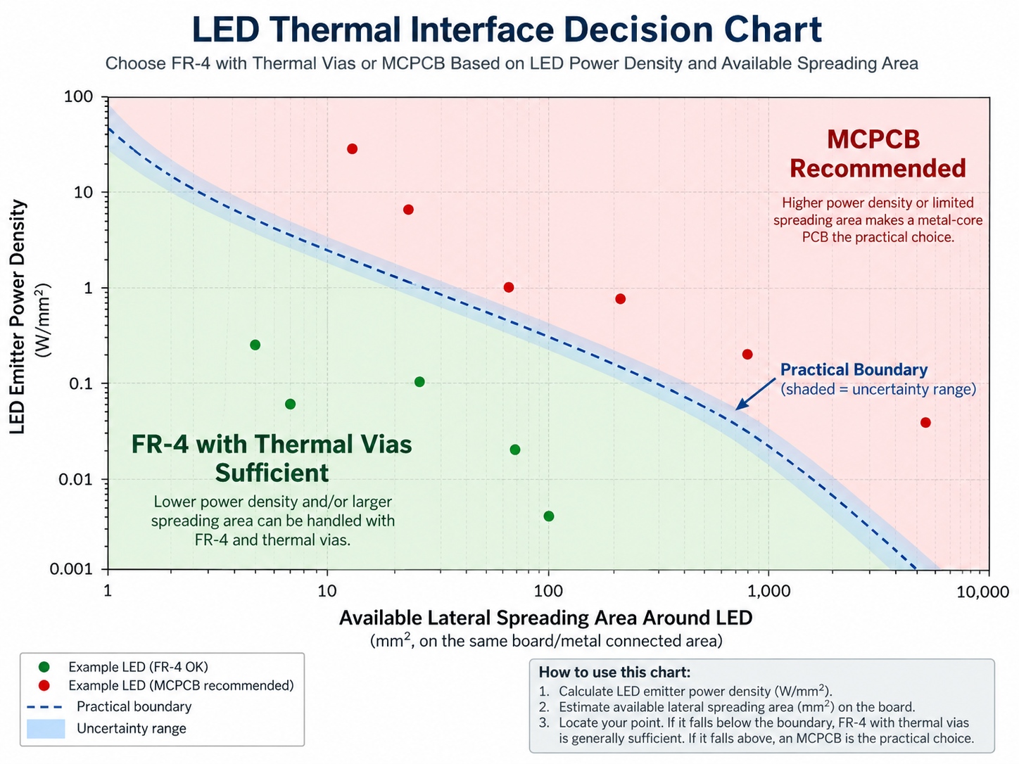
The question of when to use a metal core PCB for LEDs is really a question about power density and available spreading area. A single low-power indicator rarely justifies a metal-core board. As emitter count grows and the dies are packed closely, the heat that must cross a small area increases sharply, and lateral spreading becomes as important as vertical conduction. Dense arrays and multi-die packages are where the metal base earns its cost.
Mechanical and cost trade-offs
Metal-core boards are heavier, stiffer and need different machining, and they constrain how densely you can route control circuitry. Many successful designs use a hybrid approach, keeping logic on FR-4 and placing the emitter array on a separate metal-core board so that each substrate does the job it is good at.
HOUKEM's confirmed high-power LED capability extends up to 1600W for applicable model and project configurations, and the actual wavelength, power and package combination is confirmed per project rather than assumed from the platform maximum. How the resulting heat is removed at that scale is discussed in our guide to cooling high-power UV LEDs, which follows the same junction-to-coolant logic used for other high-power emitters.

How to Decide Without Full Thermal Simulation
You do not need a full model to make the first substrate decision. Working backwards from the junction temperature is usually enough to separate the two cases.
Start from the permissible temperature rise
Set the maximum junction temperature the design can tolerate and subtract the expected ambient inside the enclosure. The remainder is the total thermal budget for every layer between junction and air. Estimating the junction temperature from the datasheet and your own board layout is a short calculation, and our walkthrough on calculating LED junction temperature shows how to combine power dissipation with the applicable thermal path.
Compare the full path, not one number
A substrate change only pays off if the board is genuinely the limiting element. If the enclosure already blocks airflow, or the heatsink interface is poorly controlled, moving to a metal-core board will shift cost without shifting temperature. Model the chain from junction to ambient first, then improve the weakest link.
Substrate Selection Checklist
| Check | Signals FR-4 is still viable | Signals MCPCB is the safer choice |
|---|---|---|
| Emitter power density | Low, spread over a comfortable area | High, or several dies clustered under one lens |
| Thermal budget after ambient rise | Comfortable margin remains after other layers | Budget is already tight before the board is considered |
| Board area available for vias | Enough room for a dense, well-plated via field | Pad area is small, so via count cannot be increased |
| Lateral spreading needed | Heat is removed close to each emitter | Heat must be spread across a wider area |
| Mechanical and assembly constraints | Weight, thickness and machining favour laminate | Stiffer base and different machining are acceptable |
| Control circuitry on the same board | Logic and emitter share a substrate comfortably | Splitting into two boards is acceptable or preferred |
Document the outcome of this checklist in the design record. If a later revision raises power without revisiting the substrate, the checklist is what makes the omission visible.
Frequently Asked Questions
Is an MCPCB always better than FR-4 for LEDs?
No, because a metal-core board adds cost, weight and layout constraints that a low-power design does not need. It becomes the better choice only when the board is genuinely the limiting element in the thermal path.
Can thermal vias make FR-4 good enough for high power?
They can help substantially when there is enough area for a dense, well-plated via field under each pad. Once the pad area is too small to support that field, vias stop being an adequate substitute for a metal base.
Does the substrate affect light output or colour?
It affects them indirectly, because junction temperature shifts both output and wavelength. A substrate that keeps the junction cooler therefore helps stabilise the optical performance the design was specified around.
How do I know which layer is the real bottleneck?
Compare the thermal resistance of each element in the chain from junction to ambient. The largest term is the one worth improving, and it is frequently the interface or the enclosure rather than the board itself.
Can one design use both substrates?
Yes, and it is common practice. Placing the emitter array on a metal-core board while logic remains on FR-4 lets each substrate do the work it handles best.

Conclusion
FR-4 and MCPCB are not competing for the same job. FR-4 serves control circuitry and moderate emitters well, while a metal-core board exists to give high power density a shorter and wider route to the mounting surface. Decide by working backwards from the junction temperature and comparing the whole thermal path, not by comparing a single material property.
If your project includes high-power emitters and you need the substrate, package and thermal arrangement reviewed against a real build, send your requirements to the HOUKEM team and we will confirm what applies to the specific configuration.
Peak Wavelength vs Dominant Wavelength: What Each Value Tells You