How to Cool High-Power UV LEDs

Quick Answer
Cool high-power UV LEDs by treating the thermal path as a chain of series resistances and finding the weakest link, rather than by adding a larger heatsink. Work from the die attach and package, through the board and substrate, to the interface and cold plate. Because UV emitters convert a smaller share of electrical power into optical output than visible emitters, proportionally more becomes heat at the junction, and the bond line and mounting interface usually dominate the total resistance. Choose passive cooling for modest drive levels, forced air for mid-range arrays, and liquid or cold-plate cooling where the array is dense or output must stay stable over long duty cycles.
Why UV LED cooling is a different problem
A smaller share of input power leaves as light
For any LED, the heat to be removed is the electrical input minus whatever leaves as optical output. In UV devices the conversion efficiency is generally lower than in mature visible emitters, and it varies further with wavelength and drive current, so a larger fraction of the input power arrives at the junction as heat. A UV LED and a visible LED with the same electrical rating therefore do not impose the same thermal load per unit of useful output, and designing to an electrical rating alone is a common way to under-size the thermal solution.
Package geometry and wavelength constrain the path
UV emission pushes designs toward packages with good optical extraction, sometimes with a window or lens arrangement that limits the area available for direct thermal contact. Shorter wavelengths also raise material compatibility questions for encapsulants, optical elements and coatings, which can restrict the designs available for spreading heat, so the thermal path is frequently narrower than in an equivalently rated visible part and the design must compensate below the package rather than inside it.
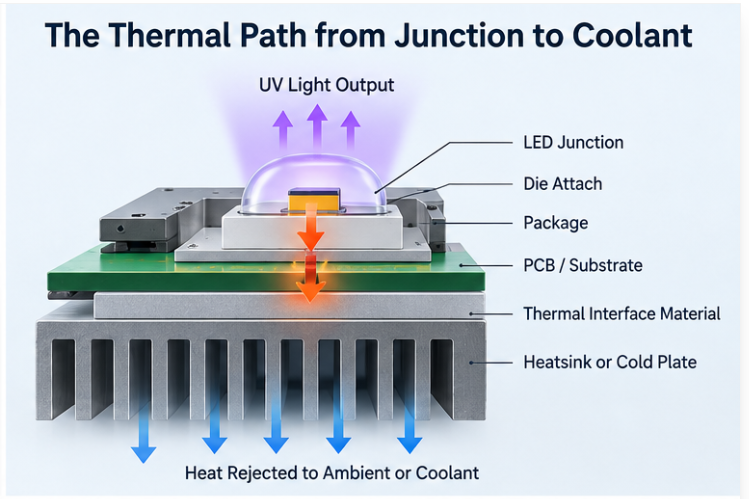
The thermal path from junction to coolant
Die attach and package
The first stage runs from the junction through the die attach into the package body. This resistance is set by the manufacturer and cannot be improved downstream, so take it from datasheet conditions rather than assumption. Where a device is offered in several package variants with different thermal characteristics, the choice of package is a thermal decision as much as an optical one.
Board, substrate, interface and heatsink
Below the package, the board determines how effectively heat spreads before it reaches the mounting surface; metal-core boards and thermally enhanced substrates exist precisely because a standard laminate cannot move the required heat away from a small contact area, and this is the stage where a designer usually has the most freedom. The final stage crosses the mounting interface into the heatsink or cold plate, where interface material, bond-line thickness and mounting pressure dominate, and those are the most frequently under-specified part of a UV thermal design. A high-performance heatsink connected through a poorly controlled interface performs worse than a modest heatsink connected properly.
Choosing a cooling approach
The deciding variables are the heat load at the junction, the maximum junction temperature you will accept, the available coolant temperature, the space envelope and the duty cycle. Decide the acceptable junction temperature first, since it sets both the thermal budget and the expected optical behaviour over time.
Passive and forced-air cooling
Passive solutions rely on conduction into a heatsink and natural convection from its surface; they are simple, quiet and maintenance-free, and suit lower drive levels, intermittent duty and generous space, but their limit is the rate at which the heatsink rejects heat to still air. Adding airflow raises the heat rejection rate of the same heatsink substantially and is usually the cheapest way to extend the usable drive range of an array. It brings moving parts and a dependency on airflow continuity, since a blocked filter or failed fan silently degrades the thermal margin, so the control system should detect its absence rather than assume it.
Liquid and cold-plate cooling
Where the array is dense, the duty cycle long, or output must remain stable, liquid cooling becomes practical because it moves heat away from the emitter at a much higher rate and with a smaller temperature rise per watt. It adds pumps, seals, fluid management and condensation risk where surfaces run below the dew point, and those constraints belong in the design review rather than in commissioning. HOUKEM's confirmed high-power LED capability extends up to 1600W for applicable model and project configurations, and at that level the thermal design, not the optical design, normally sets the achievable output.
Design details that decide the outcome
Control the interface, then verify by measurement
Specify the interface as a controlled parameter: material type, applied thickness and the mounting pressure or torque that achieves the intended bond line, verified in production rather than only on the first prototype. An estimated thermal resistance then gives a starting point, while the case temperature under real conditions gives the check, so instrument the case in the actual enclosure with the actual airflow or flow rate. Take that measurement at the centre of the array under the worst sustained duty cycle, because individually well-cooled emitters can still fail as an array: neighbouring devices heat each other and the centre of a densely packed array runs hotter than the edges.

Where UV cooling projects go wrong
- The optical share of the input power is ignored. The thermal load is under-estimated from the start.
- The heatsink is upgraded before the interface. Money is spent on area while the bond line remains the dominant resistance.
- The calculation is trusted without a case measurement. Real enclosure behaviour is never verified.
- An edge device is checked, or duty cycle is ignored. A measurement at the periphery flatters the design, and a steady-state estimate is applied to an application whose binding condition is a repeated burst.
Frequently Asked Questions
Why do UV LEDs need more cooling than visible LEDs of the same power?
A smaller share of the electrical input leaves a UV emitter as optical output, so proportionally more of the input becomes heat at the junction. The difference varies with wavelength and drive current, so the thermal load should be established for the specific device rather than transferred from a visible part.
What is the most common cause of poor UV LED cooling?
The mounting interface, including material choice, bond-line thickness and mounting pressure, is the most common weak link. A high-performance heatsink connected through an uncontrolled interface under-performs a modest heatsink connected properly.
Is liquid cooling necessary for high-power UV LEDs?
It becomes necessary when the array is dense, the duty cycle long, or output stability critical, because it removes heat with a much smaller temperature rise per watt. It also adds pumps, seals, fluid management and condensation risk, so it should be chosen on those grounds rather than on rated power alone.
How should I verify a UV LED thermal design?
Measure the case temperature in the actual enclosure under the real airflow or flow rate, and compare it against the calculated estimate. Take the measurement at the centre of the array under the worst sustained duty cycle, because that position runs hotter than the edges.
Does a bigger heatsink always reduce junction temperature?
Only until the interface and the board become the limiting stages. Beyond that point the additional area produces little improvement, and the effort is better spent on the interface, the substrate or the airflow path.
What duty cycle information matters for UV cooling design?
The worst sustained on-period matters more than the average, because the junction approaches its peak temperature during that interval. State the duty cycle pattern explicitly and design for its hottest sustained condition rather than for a long-term average.
Conclusion
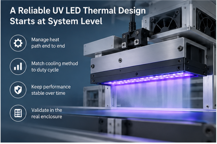
Effective UV LED cooling comes from finding and fixing the weakest stage in the junction-to-coolant path, not from adding thermal mass. Establish the heat load from the electrical input minus the optical share, work through die attach, substrate and interface in order, and decide the cooling method from the acceptable junction temperature, the environment and the duty cycle.
If the thermal path is the constraint in your UV system, send your project requirements and the applicable specification so the wavelength, power and package combination can be confirmed for your configuration. HOUKEM is an LED manufacturer established in 2003 with a UV LED range spanning 255 to 415nm at the top level, and exact wavelength, power and package combinations are confirmed per model and project.
940nm vs 980nm IR LED: Differences and Applications
UV LED Irradiance vs Dose: What Curing Engineers Need to Know