


How to Choose the Right LED Driver for UV and IR LEDs
Choosing an LED driver for a UV or IR system starts with the LED datasheet, not the wattage printed on the power supply.
The key questions are straightforward: What current does the LED require? What is its forward-voltage range? How many LEDs are connected in series? What input voltage is available? Will the LEDs run continuously or in pulses?
For most discrete high-power UV and IR emitters, a constant current LED driver is the normal starting point because LED output is primarily controlled by current. But that does not mean every UV or IR project uses the same driver. A UV curing array running continuously has very different requirements from an IR illuminator synchronized with a machine-vision camera.
This guide explains how to choose the right LED driver for UV and IR LEDs, with a practical focus on current, voltage, driver topology, thermal conditions, PWM control, and OEM system design.
What Type of Driver Do UV and IR LEDs Need?
In most high-power applications, bare UV and IR LEDs are driven with regulated constant current rather than a fixed-voltage supply.
A suitable driver must do two things at the same time:
Maintain the required LED current and provide enough output voltage to cover the full forward-voltage range of the LED string.
The basic selection logic is:
| System Condition | Typical Driver Choice |
|---|---|
| High-power UV LED | Constant-current driver |
| High-power IR LED | Constant-current driver |
| Input voltage higher than LED string voltage | Buck driver |
| Input voltage lower than LED string voltage | Boost driver |
| Input voltage may move above and below LED voltage | Buck-boost driver |
| Continuous UV curing | Stable current and strong thermal control |
| IR sensing or machine vision | Fast switching, PWM or pulse capability may be required |
| Integrated LED module with onboard regulation | Follow the module input specification |
This distinction is important. A bare high-power LED and a complete LED module may look similar from the outside, but their electrical requirements can be very different.
Why Constant Current Is Usually Preferred
LEDs are not resistive loads. Their current can change sharply with relatively small changes in voltage.
Forward voltage, or Vf, also changes with temperature and varies slightly from one LED to another. If a bare high-power LED is connected directly to a fixed-voltage source without suitable current regulation, the operating current can become difficult to control.
That is why a constant current LED driver is commonly used for high-power UV and IR emitters.
The driver regulates the current while allowing its output voltage to move within a defined operating range.
A constant-voltage supply, by contrast, is more appropriate when the LED assembly already includes resistors, current regulators, or driver electronics.
So the practical question is not simply:
“Constant current or constant voltage?”
It is:
“Does this LED or module already contain current-control circuitry?”
For a discrete UV or IR LED, the answer is usually no, which makes regulated current particularly important.
Start With Forward Current, Not Wattage
One of the most common driver-selection mistakes is choosing by wattage alone.
Suppose a product is described as a 20W LED. A 20W driver is not automatically compatible with it.
The engineer still needs to know the required:
Forward current, forward voltage range, input voltage, output-voltage window, operating mode and thermal conditions.
The LED datasheet should therefore be the first reference point.
If the specified forward current is 700mA, the driver should regulate near that level unless the design intentionally operates the LED below its rated condition.
It is also important to distinguish between continuous current and peak pulse current.
A peak current rating may only apply for a very short pulse at a specified duty cycle. It should never be treated as a continuous operating current unless the datasheet explicitly permits it.
Correct LED driver current matching becomes even more important with high-power UV and IR LEDs because additional current quickly increases heat generation.
Check the Full LED Forward-Voltage Range
Current determines how the LED is driven, but voltage determines whether the driver can actually regulate it.
Do not look only at a single typical Vf value.
Where available, check:
Minimum Vf, typical Vf, maximum Vf, test current and test temperature.
This matters because the driver must have enough compliance voltage to operate the LED across normal manufacturing and temperature variation.
Consider an LED specified at 3.4V typical and 3.8V maximum. A driver whose output range stops below 3.8V may work under some conditions and then fall out of regulation as the actual LED voltage changes.
That is why LED forward voltage and current should always be evaluated together.
Calculate the Voltage of the Complete LED String
When LEDs are connected in series, their forward voltages add together.
The basic calculation is:
Total string Vf = Vf per LED × number of LEDs in series
If four UV LEDs each have a forward-voltage range of 3.4V to 3.8V, the string requires approximately:
13.6V to 15.2V
A suitable driver must therefore regulate the required current while supporting at least that output-voltage range.
The same principle applies to IR LED arrays.
Parallel designs need more care because LEDs rarely have exactly identical Vf characteristics. Without proper current balancing, one branch may carry more current than another.
For high-power systems, series strings or separately regulated channels are often easier to control than simply placing unmatched LEDs in parallel.
Buck, Boost or Buck-Boost?
Once the LED current and string voltage are known, compare them with the available input supply.
A buck driver reduces voltage and is typically used when the input voltage stays above the LED-string voltage.
For instance, a 24V supply driving a 15V UV LED string is a typical buck-driver situation.
A boost driver raises voltage and is used when the source voltage is lower than the required LED-string voltage.
This can occur in battery-powered equipment where a relatively low battery voltage must drive several LEDs in series.
A buck-boost driver becomes useful when the supply may move above and below the LED-string voltage during operation.
Battery systems are a common example. As the battery discharges, its voltage may cross the level required by the LED string. A buck-boost architecture can maintain regulation across that wider range.
Choosing the topology from these voltage relationships is more reliable than selecting a driver based on a generic “high power LED driver” label.
UV LED Driver Selection: Prioritize Stability and Heat
A UV LED driver is often used in systems where optical output must remain consistent over relatively long operating periods.
Typical applications include UV curing, inspection, fluorescence excitation, printing and industrial processing.
In these systems, current stability matters because changes in LED current can affect radiant output. Temperature matters for the same reason.
A UV LED may still be electrically operating while its optical performance changes because the junction temperature has increased.
For continuous or high-duty-cycle systems, engineers should therefore evaluate driver efficiency, current accuracy, output ripple, thermal derating and heat-sink capability together.
This is especially important in UV LED power supply selection. A driver that is electrically compatible on paper can still perform poorly in a tightly enclosed system with insufficient cooling.
For curing applications, stability can also affect process consistency. If optical output changes significantly during operation, curing results may vary from one production cycle to the next.
IR LED Driver Selection: Consider Pulse and Timing Requirements
An IR LED driver may have a different operating profile.
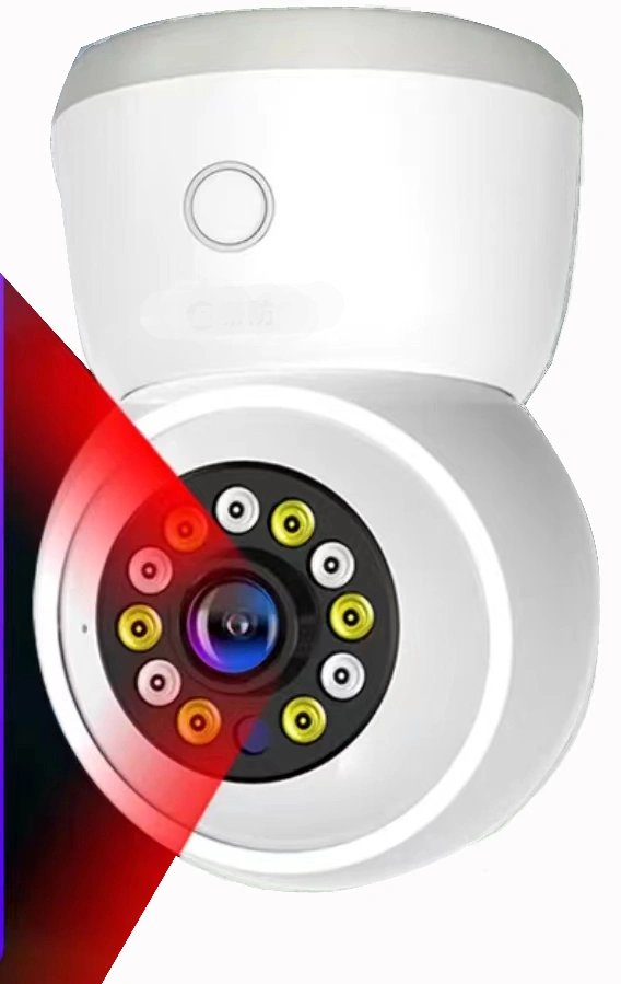
Security cameras often use relatively long periods of IR illumination, while machine-vision, proximity-sensing and optical-detection systems may drive the LEDs in short pulses.
In pulsed applications, the driver may need to provide fast current rise and fall times, accurate pulse amplitude and synchronization with a sensor or camera.
A PWM LED driver for IR LED systems may also need to support the required switching frequency and duty cycle without distorting the optical pulse.
Peak current can sometimes be higher than the normal continuous current, but only when the LED datasheet defines an allowable pulse condition.
The key parameters are not just peak current. Pulse duration, repetition rate, duty cycle and thermal accumulation all matter.
This makes IR driver selection particularly application-dependent.
An IR illuminator for CCTV and an IR emitter used in a high-speed optical sensor may use the same wavelength but require very different driver behavior.
Example: Matching a Driver to a UV LED String
Consider four UV LEDs connected in series.
Each LED is specified at:
Forward voltage: 3.4V to 3.8V
Forward current: 700mA
The string voltage is therefore:
3.4V × 4 = 13.6V
to:
3.8V × 4 = 15.2V
The driver should regulate approximately 700mA and provide an output-voltage range that comfortably covers 13.6V to 15.2V.
If the system uses a stable 24V DC supply, a buck constant-current driver would normally be a logical starting point.
Now compare that with a high-power IR array requiring tens of volts and more than 1A of current. The same driver clearly would not be suitable.
This is why how to choose an LED driver should always begin with the actual LED electrical data rather than nominal wattage or wavelength alone.
Thermal Design Is Part of Driver Selection
A well-matched driver cannot compensate for poor thermal design.
High-power UV and IR LEDs generate substantial heat at the junction, and both electrical and optical behavior change as junction temperature rises.
The system designer should consider the complete thermal path:
LED junction → package → PCB → thermal interface → heat sink → ambient environment
Driver efficiency also matters because a low-efficiency driver adds more heat to the enclosure.
Useful protection functions may include overcurrent protection, short-circuit protection, overtemperature shutdown and open-load protection.
For compact industrial systems, thermal derating can be just as important as nominal output power.
A driver rated for a certain current under laboratory conditions may need to operate at a lower load when installed inside a hot, sealed enclosure.
Common LED Driver Selection Errors
Most driver problems can be traced back to a small number of design mistakes.
Selecting by wattage alone is one. Treating maximum current as the recommended operating current is another.
Engineers should also avoid ignoring maximum Vf, driving a bare high-power LED directly from a constant-voltage source, placing parallel LEDs together without current balancing, or using PWM without checking the driver’s switching performance.
Thermal conditions are another frequent source of trouble.
A system may pass an initial bench test and still fail after extended operation because the LED or driver reaches a much higher temperature inside the final enclosure.
That is why prototype testing should be performed under realistic operating conditions rather than only at room temperature on an open bench.
A Practical Driver Selection Workflow
For most UV and IR projects, the process can be reduced to seven steps:
Confirm forward current → check the full Vf range → calculate LED-string voltage → identify the input supply → choose buck, boost or buck-boost → verify continuous or pulsed operation → validate thermal performance
This sequence is simple, but it prevents most compatibility mistakes.
The final design should then be checked with the actual LED, driver, PCB and cooling system before mass production.
What Information Should You Give Your LED Supplier?
For OEM projects, a supplier can give better technical guidance when the application data is clear.
The most useful information includes the required wavelength, LED package or model, forward current, forward voltage, LED quantity, series or parallel configuration, available input voltage, operating mode, PWM or pulse requirements, target optical output, ambient temperature and heat-sink conditions.
These details help determine whether the LED itself is suitable and whether the proposed driver operating point is realistic.
For high-power UV and IR projects, it is often more efficient to evaluate the emitter, driver and thermal design together rather than treating them as separate components.
FAQs About UV and IR LED Drivers
Do UV LEDs need a constant-current driver?
Most discrete high-power UV LEDs are designed to operate with regulated current. Constant-current control helps keep the LED within its specified electrical range as forward voltage and temperature change. Complete UV modules may have integrated regulation, so the module datasheet should always be checked.
Do IR LEDs use constant current or constant voltage?
Bare high-power IR LEDs are commonly driven with constant current. A complete IR illuminator or module may accept a fixed-voltage input if current-control circuitry is already built into the assembly.
How do I calculate the required LED driver voltage?
Add the forward voltages of all LEDs connected in series. The driver’s regulated output range should cover the complete expected string voltage, including normal device and temperature variation.
Can I use a higher-wattage LED driver?
Yes, provided the regulated current, output-voltage range, input-voltage requirements and protection characteristics are compatible. A higher power rating by itself does not force additional power into the LED, but current regulation must still match the LED specification.
Can IR LEDs be driven with PWM or pulse current?
Yes. Many sensing, imaging and communication systems use pulsed IR operation. The LED and driver must both support the required peak current, pulse width, duty cycle and switching speed.
Choosing the Right Driver for an OEM UV or IR Project
The right LED driver for UV and IR LEDs is determined by more than voltage or wattage.
Start with the LED’s rated current and complete forward-voltage range. Then calculate the string voltage, compare it with the available supply, choose the appropriate driver topology, and confirm whether the application requires continuous, PWM or pulsed operation.
For UV systems, current stability and thermal management are often the main priorities. For IR systems, switching speed, pulse control and synchronization may be equally important.
HOUKEM supplies UV and IR LEDs for industrial and OEM applications across a wide range of wavelengths, packages and power levels. When evaluating a new project, providing the wavelength, forward current, forward voltage, LED quantity, connection method, operating mode and thermal conditions makes it much easier to identify a suitable LED and operating range.
Contact HOUKEM for datasheets, samples, wavelength recommendations and technical support for UV and IR LED projects.
UV LED Irradiance vs Dose: What Curing Engineers Need to Know
850nm vs 940nm IR LED for Industrial Sensing Applications


