


UV LED Fluorescence Inspection: Wavelength, Filters and Ambient Light

Quick Answer: Excitation In, Emission Out, Everything Else Blocked
The inspection works when a target material absorbs light in one band and re-emits it in a longer-wavelength band, and when the optical path passes the second band while rejecting the first.
Everything else in the system exists to protect that separation. Filters keep the excitation light out of the camera, working distance keeps the excitation irradiance at the required level, and mechanical shielding keeps ambient light from adding a signal the camera cannot distinguish from fluorescence.
Stated that way, the specification becomes a contrast requirement with three supporting decisions, which is what a supplier needs in order to quote a wavelength and a power rather than a generic emitter.
Choosing the Excitation Wavelength for the Target
The excitation band is set by the target material, not by the inspection station. A wavelength that excites one coating strongly may produce almost nothing on another, and the two can look identical under visible light.
Where the absorbing compound is known, the starting point is its absorption region rather than a nominal figure. Where it is not known, the practical approach is to test candidate wavelengths on representative samples and record the observed contrast rather than the emitted power, because contrast is what the inspection depends on.
The general layout of the ultraviolet bands is worth fixing before ordering anything, and the roles of the UVA, UVB and UVC regions are summarised in our overview of UV LED wavelength bands. Most industrial fluorescence work sits in the long-wave ultraviolet region, which is also where the widest choice of narrow-band emitters is available.
The chosen wavelength should then be treated as a band rather than a point. A source quoted at a nominal peak still emits across a range, and that range has to fall inside the excitation region of the target rather than straddle its edge. How far a peak can drift during operation, and how to write a tolerance around it, is covered in our explanation of UVA LED wavelength stability.
Optical Path Decisions: Filters, Placement and Geometry
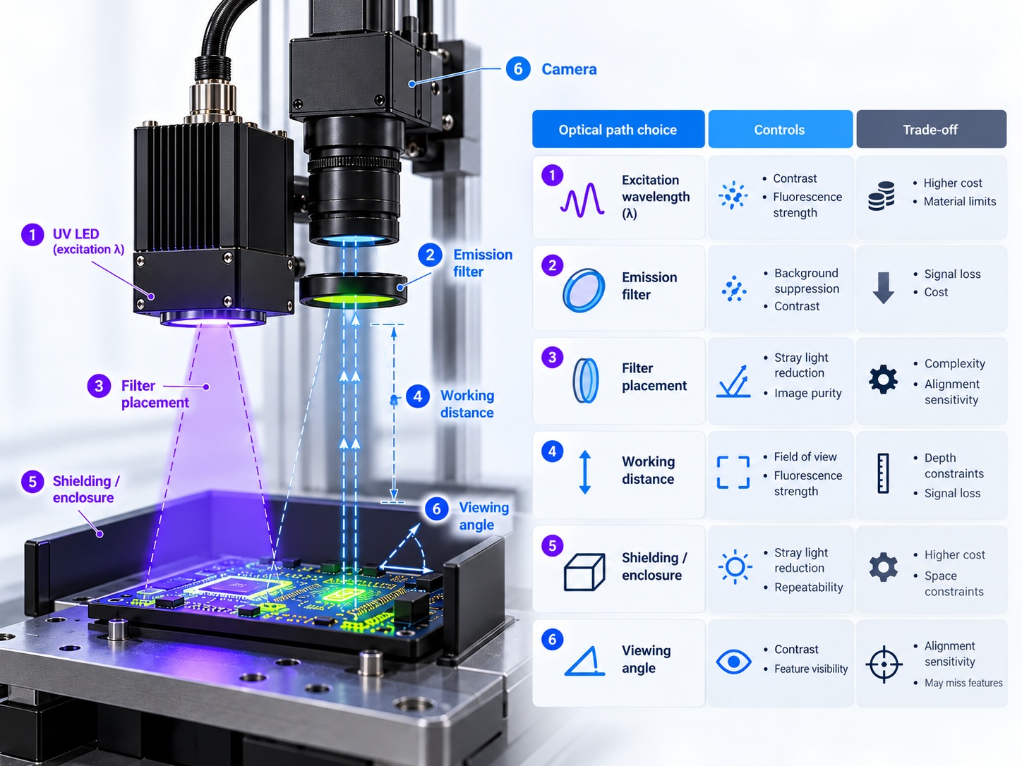
The optical path carries as much of the design as the emitter does, and the decisions interact. The table below sets out the main choices and what each one changes about the finished system.
| Decision | What it controls | Trade-off to expect |
|---|---|---|
| Excitation wavelength and bandwidth | How strongly the target absorbs | Narrower bands give cleaner separation but reduce the choice of standard sources |
| Emission filter wavelength | How much reflected light reaches the camera | A tighter filter raises contrast and lowers the collected signal |
| Filter position in the path | Whether the excitation is blocked before the sensor | Closer to the camera reduces stray light but increases alignment sensitivity |
| Working distance | Irradiance on the target and field size | Shorter distances raise irradiance and narrow the usable field |
| Beam uniformity | Whether contrast is constant across the part | Uniform coverage usually needs a larger array or additional optics |
| Mechanical shielding | How much ambient light reaches the target | Enclosure complexity rises as the required contrast rises |
The relationship between distance and irradiance is the one most often underestimated, because a small change in mounting height moves the signal more than a large change in drive current. The behaviour is set out in our guide to how working distance changes irradiance, and it applies to an inspection head exactly as it does to a curing head.
Ambient Light and the Signal-to-Noise Problem
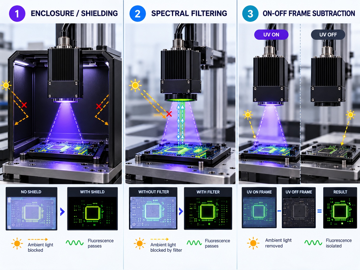
Ambient light enters the system through the same aperture as the fluorescence, and it does not look different to the camera. A fluorescent ceiling fitting or a nearby inspection lamp can contribute more photons than the target does, which is why ambient control is a design decision rather than a housekeeping detail.
Three measures address it, and they are usually combined. The first is enclosure, which removes ambient light geometrically instead of optically. The second is spectral, which relies on the emission filter already in the path to reject the wavelengths that ambient sources emit most strongly. The third is temporal, which compares a frame taken with the excitation on against one taken with it off and subtracts the difference.
The temporal method is powerful but it constrains the mechanical design, because the source must switch cleanly and the part must be stationary between the two frames. Where the line is running continuously, that constraint is often the deciding factor between a simple enclosure and a more complex measurement sequence.
The practical objective is a working contrast margin, not a maximum signal. A system that produces a bright image at the start of a shift and a marginal one at the end has no usable margin, and the fix belongs in the optics rather than in the exposure setting.
What to Send a Supplier Before You Specify
A supplier can only verify a wavelength choice against the information they are given, so the quality of the requirement decides the quality of the answer.
The four inputs that change the recommendation most are the target material or the compound responsible for the fluorescence, the required contrast and the feature size being inspected, the available space and working distance, and the ambient conditions at the station. A drawing of the mounting envelope is more useful than a description of it, because the geometry decides whether a single emitter or an array is the sensible starting point.
It is also worth stating what the inspection must not do. If the source must not expose operators to ultraviolet radiation, or must not illuminate beyond the inspection zone, those constraints change the shielding and the enclosure rather than the emitter, and they are easier to accommodate at the specification stage than after the station is built.
Where the requirement is narrow and the application is unusual, the emitter choice is usually confirmed on a sample rather than from a datasheet, because the excitation efficiency of a specific compound cannot be inferred from a published curve. Uniform coverage across the inspection area matters as much as peak output, because a bright spot leaves the rest of the part unread.
Frequently Asked Questions
How to specify UV LED fluorescence inspection for an OEM application?
Start from the target material and the contrast the inspection needs, then derive the excitation band, the emission filter and the working distance from it. State the mounting envelope and the ambient conditions so the geometry can be checked before the emitter is chosen.
Which parameters matter most for UV LED fluorescence inspection?
The excitation band and the emission filter matter most, because together they decide how much of the reflected light reaches the sensor. Working distance and beam uniformity come next, because they decide whether that contrast holds across the whole part.
How to validate UV LED fluorescence inspection in the final product?
Validate on the actual target with the actual optics, the actual filter and the actual enclosure in place, and measure contrast rather than brightness. Repeat at the start and end of a production run to confirm the margin is still there.
What should engineers send a supplier for UV LED fluorescence inspection?
Send the target material, the required contrast and feature size, the mounting envelope with the intended working distance, and the ambient conditions at the station. Adding the operator-safety constraint early avoids redesigning the shield later.
Is a brighter source always better for inspection?
No, because reflected excitation light grows with the source as well, so a brighter emitter can reduce contrast even while it increases illumination. The gain comes from filter separation and geometry, not from raw output alone.
Conclusion: Specify Contrast, Not Illumination
UV LED fluorescence inspection is specified by the contrast at the target, and the emitter is only one of the components that produce it. Fix the excitation band, the filter arrangement and the ambient control together, and the configuration follows from the requirement rather than from whatever source happens to be available.
The approach also makes UV Industrial Applications work reproducible, because UV LED system design and UV process engineering inputs are recorded with the optics and geometry they were chosen for. That is what allows a second station to be built to the same contrast rather than to the same parts list.
If you are specifying an inspection light source and want the wavelength, package and geometry options confirmed for the actual target, review the UV LED products range and send the requirement through the inquiry page.
UV LED Radiometer Selection: Matching the Instrument to the Measurement


