UV LED Working Distance: How Distance Changes Irradiance at the Target

What Working Distance Actually Changes
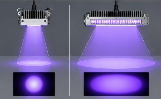
A UV LED emits into a cone, so the emitting surface and the illuminated surface are linked by geometry. When the head is raised, the same optical power is spread over a larger area and the irradiance at any point inside that area falls; when the head is lowered, the illuminated area shrinks and the center of the pattern becomes more intense. The inverse-square relation is a reasonable first estimate for a small source measured at a long distance, but real curing heads use arrays, lenses or reflectors, so the practical way to treat UV LED working distance in any UV LED system design is as a measured input rather than a calculated constant. The distinction matters because intensity and delivered energy are different quantities: irradiance versus dose explains how time interacts with intensity, and a head that produces high peak irradiance very close to the part can still under-cure a fast-moving substrate.
Which Parameters Matter Most for UV LED Working Distance
Which parameters matter most for UV LED working distance? The first is the optical design of the head, because beam angle, secondary optics and emitter spacing decide how quickly the pattern degrades with height. The second is the area the process actually needs to expose, which sets the minimum height at which the whole target is still covered. The third is the acceptable spread between the brightest and dimmest point on that area, which is a uniformity question rather than a single-number question. The fourth is thermal behavior, because a head moved closer to the part also moves its heat closer to the part. The table below summarizes how these inputs interact.
| Parameter | Where It Comes From | Effect on the Distance Decision |
|---|---|---|
| Beam angle and optics | Emitter type, lens, reflector or protective window | Sets how quickly the pattern widens and how fast peak irradiance falls |
| Required exposed area | Part size, conveyor width, process tolerance | Defines the shortest height at which the whole target is covered |
| Acceptable uniformity | Process specification and coating or adhesive behavior | Limits how far the pattern may spread before results drift across the part |
| Required irradiance | Formulation, line speed, target dose | Bounds the height from above, because intensity falls with distance |
| Thermal load at the part | Emitter power, duty cycle, head temperature | Bounds the height from below when the substrate is heat sensitive |
How Distance Interacts with Optics and Beam Geometry
Within the wider discipline of UV System Geometry & Optical Design, working distance is the link between the source and the process. A collimated head holds its footprint over a useful range, which makes height less critical and alignment more critical; a bare or wide-angle array spreads quickly, which turns height into a major process variable. Emitter spacing adds a second dimension, because elements that overlap cleanly at one height may leave gaps or hot spots at another. Wavelength selection interacts here as well, since a formulation that absorbs strongly at a given band needs less exposure time at a lower head position; choosing a UV LED curing wavelength is the first decision, and working distance is how that decision is delivered to the part. On high-power systems the physical envelope of the head limits how close it can be mounted, because high-power 365nm UV LED modules need a thermal path and mechanical clearance that a small indicator emitter does not.
How Does UV LED Working Distance Affect LED Performance
How does UV LED working distance affect LED performance? It does not change the emitter itself, but it changes every result the line can measure: surface irradiance, uniformity across the part, cure speed and the temperature the substrate reaches. That is why the height belongs in the process window alongside line speed, dose and wavelength rather than in the mechanical drawing alone. UV process engineering is largely about holding such a window repeatably, so the setting should be recorded with the same discipline as the other parameters. Head cooling belongs to the same conversation, because emitter output falls as the die warms and the heat load at the target rises with proximity; cooling high-power UV LEDs covers the thermal side of that trade-off.

How Should Engineers Validate UV LED Working Distance Before Production
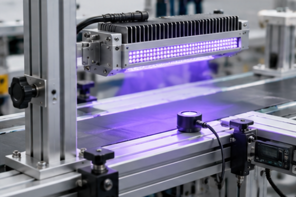
How to evaluate UV LED working distance for an OEM design starts from the process requirement rather than from the fixture drawing. Define the minimum irradiance and the maximum acceptable variation across the exposure area, then measure the head at three heights: the mechanically shortest position, the intended production position and one step further away. Measure with a calibrated instrument instead of inferring intensity from cure results, matching the sensor to the wavelength band in use; measuring UV LED optical power describes that setup in detail. Repeat the sweep after the head has reached thermal steady state, because output drops as the emitters warm, and record each result next to the line speed so the delivered dose can be reconstructed later. That is how should engineers validate UV LED working distance before production: as a short recorded height sweep with pass limits and a date, not as a one-off observation on the bench.
Frequently Asked Questions
Does moving the head closer always give a faster cure?
Closer usually raises irradiance near the center of the pattern, which raises the delivered energy at a fixed line speed. It also shrinks the covered area, so a part larger than the footprint can receive less energy at its edges rather than more.
Is the inverse-square rule enough to set the height?
It is a useful starting estimate for a small source measured far away, but arrays, lenses and reflectors change the real distribution. Measure the actual head instead of relying on the formula alone.
How much height variation is acceptable in production?
The tolerance should come from how much irradiance change the process still tolerates, not from the mechanical accuracy that happens to be available. Convert the allowed irradiance band into a height band during the sweep.
Should the height be set with the head cold or warm?
Set and verify it at thermal steady state, because emitter output falls as the die temperature rises. A cold bench measurement overstates the irradiance the line will see after warm-up.
Does a wider beam mean better uniformity?
A wider beam covers more area but usually drops off more gently at the edges only if the emitters overlap properly. Uniformity depends on array spacing and optics, so it has to be measured rather than assumed.
Bringing the Geometry Together
A usable working distance is the product of an optical design, a required exposure area, an acceptable uniformity band and a thermal limit, and it should be confirmed by measurement rather than by drawing alone. Handled that way, UV LED working distance becomes a documented process parameter instead of a mechanical detail that quietly decides the result. If you are specifying UV LED sources for a curing or inspection system and want the optical and thermal parameters confirmed against a real project, send your requirements to HOUKEM and the engineering team will support the design-in.
UV LED Irradiance Uniformity: How to Map Hot Spots Across the Curing Area
How to Measure IR LED Output: A Practical Measurement Framework