How to Use IR LED Components: Circuit Basics, Drive Setup and Wiring

What an IR LED Does Before You Wire It
An IR LED converts forward current into infrared light instead of visible light, which means every check you would apply to a visible LED still applies, plus one more: you cannot see the output. Common near-infrared parts emit around 850nm or 940nm, while extended-capability devices reach further into the infrared. HOUKEM builds infrared emitters across its wider infrared LED product family, where confirmed capability extends to 1900nm for applicable projects and the exact wavelength, power and package combination is confirmed per project.
Because the output is invisible, plan the verification method from the start. A phone camera or a photodiode test will show whether the emitter is running, and the dedicated checks are set out in how to test an IR LED. Deciding the test method before the first prototype saves a lot of guessing later.
The Basic IR LED Circuit
A basic IR LED circuit needs only three elements: a supply, the emitter, and an IR LED current limiting resistor in series. The resistor sets the IR LED drive current almost entirely, because the diode forward voltage stays roughly fixed at about 1.2 to 1.6 volts for typical near-infrared parts. Ohm's law does the rest: subtract the forward voltage from the supply, divide by the target current, and pick the next standard resistor value.
| Circuit element | What it does | What to check before build |
|---|---|---|
| Supply rail | Provides the drive voltage | Headroom above the forward voltage at the target current |
| Current limiting resistor | Sets the operating current | Power rating, not only resistance value |
| IR LED | Converts current into infrared output | Wavelength, viewing angle and package fit |
| Return path | Closes the current loop | Track width and solder joint quality |
Two details are easy to skip. First, the resistor dissipates real power, so a part running at 100mA from a 5V rail needs a resistor rated for that duty rather than the smallest package on the shelf. Second, the IR LED viewing angle changes how much output actually reaches the target, so a narrow-angle part and a wide-angle part with identical radiant output behave very differently once they sit inside an enclosure.
How to Connect an IR LED to a Microcontroller
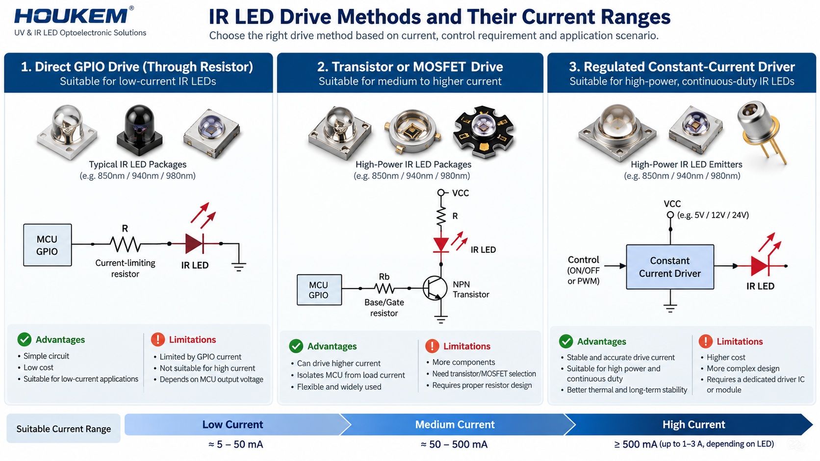
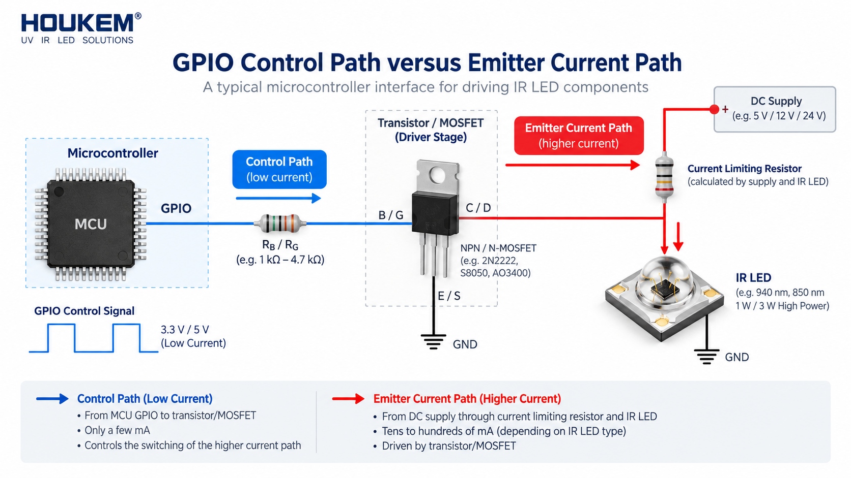
For low currents, a GPIO pin can drive the emitter through the resistor directly, but most microcontroller pins are rated well below the currents an illumination job needs. The usual pattern for how to connect an IR LED to a microcontroller is therefore a small transistor or MOSFET between the pin and the emitter, with the pin driving the base or gate and the supply providing the actual current. Add a base or gate resistor, keep the switching edge clean, and the same IR LED circuit rules from the previous section still apply.
When the duty cycle is high or the current reaches hundreds of milliamps, a resistor-fed circuit stops being accurate, because the forward voltage shifts with temperature and current. That is the point where a regulated driver becomes the better tool, and the selection logic is covered in LED driver for UV and IR LEDs.
Choosing the Wavelength: 850nm or 940nm in Practice
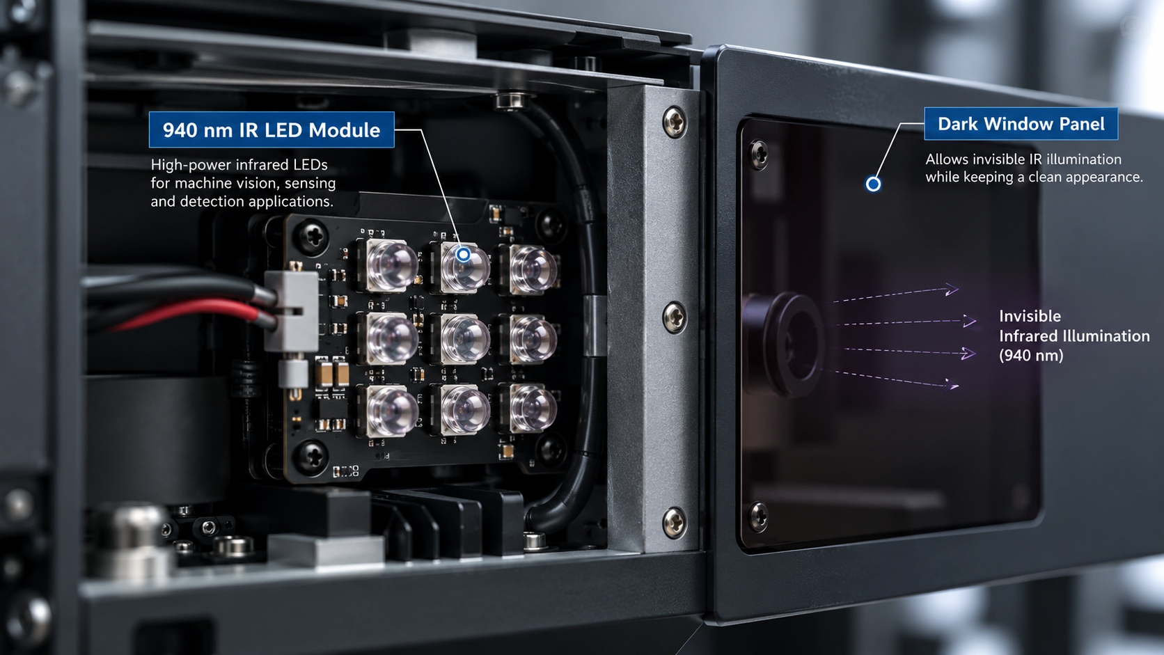
Most designs choose between two common near-infrared bands. A 940nm IR LED produces no visible red glow, which matters for products that have to look unobtrusive, while 850nm parts usually pair efficiently with common silicon receivers. The wavelength also interacts with the receiver's filter, so the emitter and detector should be chosen as a pair rather than separately. Where the application is sensing rather than illumination, the trade-offs are examined in IR LED applications across sensing and illumination.
Thermal and Layout Checks That Prevent Field Failures
An infrared emitter turns a large share of its input into heat, and because the output is invisible it does not carry visible light energy out of the enclosure. Keep infrared emitter wiring short and thermally aware, pour copper around the pads, and let the datasheet power derating curve decide the continuous current rather than the peak value. Enclosure temperature is part of the design, and the general behaviour of the heat path is explained in LED thermal management fundamentals.
If a prototype runs noticeably warm at its rated current, treat that as a layout or duty-cycle problem first. Reducing the duty cycle with pulsed drive usually restores margin without changing the emitter, and it also improves peak detection in sensing applications.
Frequently Asked Questions
What does an IR LED need to work?
A supply above its forward voltage and a series resistor that sets a safe current. With those two elements in place, the emitter behaves like any other diode load in the design.
How long does an IR LED last?
Lifespan depends mainly on junction temperature and drive current rather than on the wavelength itself. Ratings are model-specific, so confirm the documented figure for the exact part and duty cycle you plan to run.
Why does my IR LED get hot?
Most of the electrical input becomes heat inside the package, so warmth is normal at higher currents. If the part is too hot to hold its rated output, the current, duty cycle or thermal layout needs to change rather than the emitter.
Can a microcontroller pin drive an IR LED directly?
Only at the low currents the pin is rated for, which is usually enough for a proximity or indicator function. For illumination-level output, a transistor stage or a regulated driver should carry the current instead.
How can I tell if an IR LED is working?
A phone camera will usually show the emitter as a faint purple or white glow when it is driven. For a production check, use a photodiode or a purpose-built test so the result does not depend on a particular camera.
Does HOUKEM support custom IR LED requirements?
HOUKEM builds infrared emitters with confirmed capability extending to 1900nm for applicable projects. The wavelength, drive condition and package combination is confirmed per project, and the full product range carries a 2-year warranty.
Bringing the Design Together
Learning how to use IR LED parts well is less about the part and more about the three decisions around it: a resistor or driver sized for real continuous duty, a wavelength and viewing angle matched to the receiver, and a thermal layout that keeps the junction cool at production duty cycles. Projects that settle those three items early rarely meet infrared problems later.
If you are specifying an infrared emitter for a new design, share the wavelength, drive condition and enclosure constraints with the HOUKEM engineering team and send your IR LED requirement so the applicable configuration can be confirmed against your project.
How to Measure IR LED Output: A Practical Measurement Framework
LED UV Curing Systems for Printing: How to Specify Wavelength, Dose and Cooling