


How to Measure UV LED Optical Power: A Practical Guide
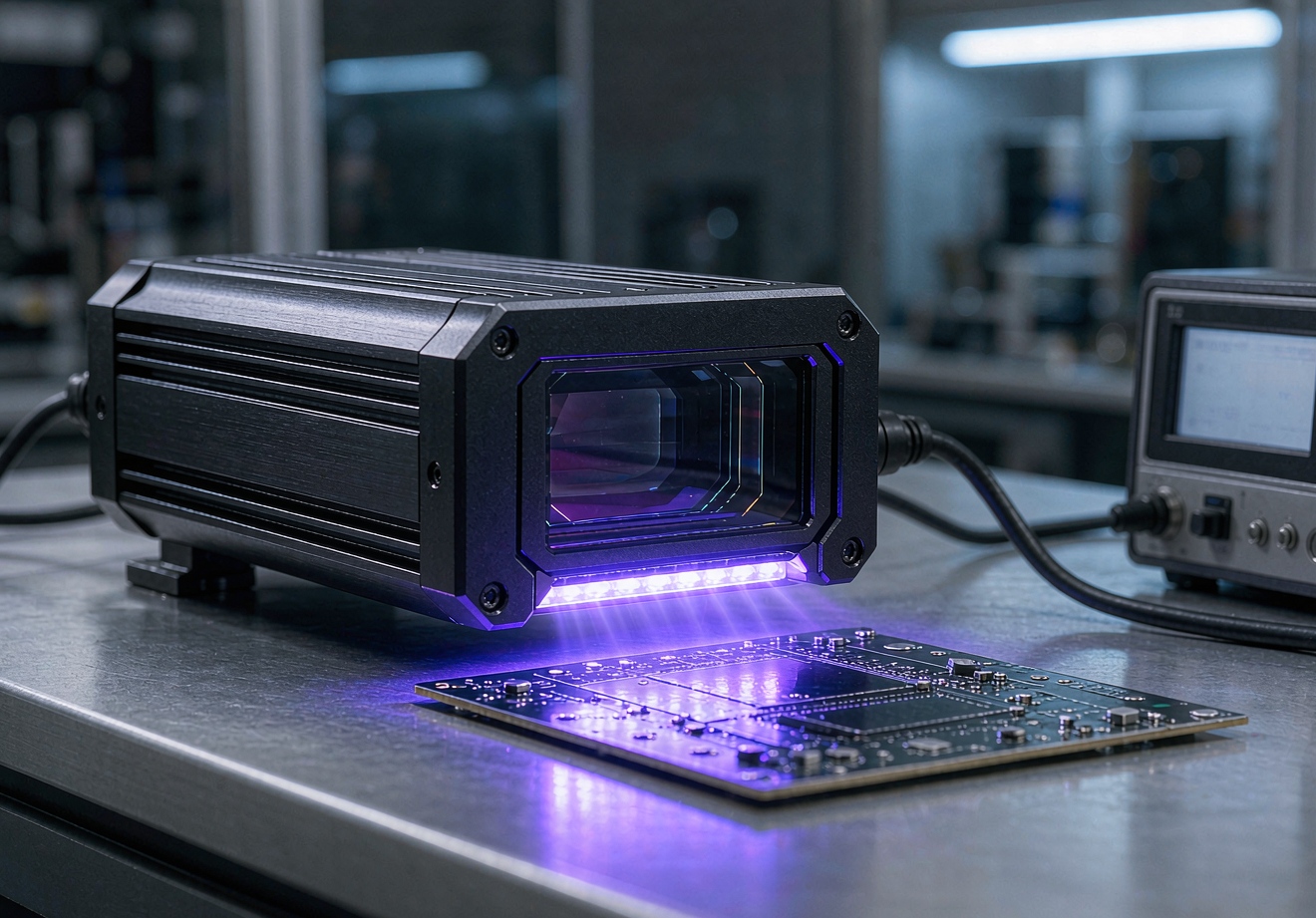
This guide explains the three quantities separately, describes the instruments used to measure each one, and gives a practical workflow you can apply before committing a UV LED design to production.
Quick Answer
To measure UV LED optical power, first decide which quantity your process actually depends on: total radiant flux in watts, irradiance in mW/cm² at the work surface, or dose in J/cm² accumulated over exposure time. Then use the matching instrument — an integrating sphere or thermopile for total power, a calibrated UV radiometer for irradiance, and a dose-logging radiometer for dose. Always record measurement distance, aperture, wavelength band and operating current alongside the reading, because the number is meaningless without those conditions.
Optical Power, Irradiance and Dose: Three Different Quantities
Most confusion in UV LED projects starts here. These terms are related but not interchangeable, and each one answers a different engineering question.
Radiant flux (optical power)
Radiant flux is the total optical power emitted by the source in all directions, expressed in watts. It answers the question "how much light does this emitter produce in total?" It says nothing about how concentrated that light is at your work surface, which is usually the quantity your process cares about.
Irradiance
Irradiance is the optical power arriving on a given surface area, expressed in mW/cm² or W/cm². It depends on the source's output, its beam angle, and the distance between source and surface. For most curing and exposure processes, irradiance at the work surface — not the source's rated power — determines process speed.
Dose (exposure)
Dose is irradiance integrated over exposure time, expressed in J/cm². A line moving under a UV head, or a part exposed for a fixed cycle, receives a dose. Two systems can deliver the same dose with very different irradiance and time combinations, and some materials respond differently to those combinations.
Instruments Used to Measure UV LED Output
UV power meters and thermopile heads
A thermopile or photodiode power meter measures radiant flux or beam power directly. This is useful for characterizing an emitter or module on the bench, especially when comparing sources across suppliers. The reading is only comparable between tests when the capture geometry, spectral response and drive current are kept constant.
Integrating spheres
An integrating sphere captures light from all directions and reports total radiant flux. For UV LEDs, the sphere coating and detector must be characterized in the relevant wavelength band. This is the standard method when a supplier states total optical power, and it is the fairest way to compare two emitters independently of optics.
UV radiometers and irradiance meters
A UV radiometer with a calibrated sensor area reads irradiance in mW/cm² at a defined distance. Because UV LED emission is spectrally narrow compared with mercury lamps, check that the meter's spectral responsivity matches your LED's peak wavelength. A meter calibrated for 365nm mercury emission can misread a 395nm LED significantly.
Dose loggers
Dose loggers record irradiance over time and report accumulated J/cm². In production they ride along the part or pass through the process window, which reveals non-uniformity along the cure path that a single spot reading misses.
A Practical Measurement Workflow
- Define the process quantity first: total flux, irradiance at the working distance, or dose per pass.
- Fix the conditions you will report: measurement distance, sensor aperture, wavelength band, drive current and substrate position.
- Choose an instrument whose spectral response covers the LED's peak wavelength, and note its calibration date.
- Take readings at several points across the cure area, not only at the center, to expose hot spots and edge falloff.
- Repeat after thermal steady state is reached, because UV LED output and wavelength shift with junction temperature.
- Log everything with the reading. An irradiance value without distance and current is not a specification.
Reading Manufacturer Specifications Correctly
Supplier datasheets may quote radiant flux, irradiance at a stated distance, or both — sometimes without the measurement geometry you need. Ask three questions before comparing numbers: at what distance and aperture was irradiance measured, over which wavelength band is the detector sensitive, and at what current and temperature was the source operating?
When you evaluate a UV LED supplier, capability statements should stay at platform level unless they are tied to a specific model. For example, HOUKEM states a UV LED top-level wavelength range of 255–415nm across its portfolio, and a confirmed high-power LED platform capability of up to 1600W for applicable model and project configurations. Neither figure describes an individual standard product: the wavelength, power and package combination for a given project is confirmed case by case. Treat any supplier number the same way — ask for the measurement condition behind it, and where the process is critical, verify irradiance at your own working distance with your own radiometer.
Common Mistakes That Distort UV LED Measurements
- Comparing watts to mW/cm². A higher-power emitter can deliver lower irradiance at the surface than a focused lower-power module.
- Ignoring spectral mismatch. Radiometers have wavelength-dependent sensitivity; a meter tuned to one UV band can misreport another.
- Measuring cold. Readings taken before the source reaches thermal steady state can overstate stable output.
- Single-point sampling. One center reading hides non-uniformity that later appears as inconsistent process results.
- Dropping the conditions. A dose or irradiance figure without distance, band and current cannot be reproduced or disputed.
Frequently Asked Questions
What unit should I use to specify a UV LED for curing?
Specify irradiance in mW/cm² at the working distance and dose in J/cm² per pass, because these describe what the material actually receives. Total radiant flux in watts is useful for comparing emitters but does not determine process speed on its own.
Can I use a mercury-lamp UV meter on a UV LED?
Only if the meter's spectral response is verified for the LED's wavelength band. UV LEDs emit in narrow bands, so a detector weighted for 365nm mercury output can produce a large error when reading a 395nm LED.
How far should the sensor be from the UV LED source?
Measure at the same distance your process will use, because irradiance falls off rapidly as distance increases. Also record that distance explicitly, since the reading is otherwise not comparable to any other test.
Does drive current change the optical power reading?
Yes, output scales with drive current, and it also drifts with junction temperature. Fix the current, wait for thermal steady state, and report both values with every measurement.
Why do two suppliers' datasheets for similar UV LEDs disagree?
They may measure different quantities, at different distances, with different detectors or at different operating points. Convert everything to the same quantity and condition before comparing, and ask the supplier for the measurement geometry when it is missing.

Conclusion
Measuring a UV LED source is less about the instrument and more about the discipline of naming the quantity, fixing the conditions and reporting them with the number. Teams that specify irradiance at the working distance, verify with a spectrally matched radiometer, and log current and thermal state avoid most specification disputes before they start. The same discipline applies when reading supplier datasheets: every optical figure is only as meaningful as the geometry behind it.
If you are evaluating UV LED sources for an industrial process and need irradiance or dose figures tied to your actual working distance, submit your process parameters to the HOUKEM engineering team through the inquiry page. The team can confirm applicable wavelength, power and package configurations for your project and specify the measurement conditions for verification.
IR LED Radiant Intensity Explained for Engineers
940nm vs 980nm IR LED: Differences and Applications


