IR LED Above 1000nm: Detector, Optics and Power Considerations for OEM Design

This guide explains what an IR LED above 1000nm changes in practice, which parameters carry the design decision, and how to validate the choice before production rather than during it.
Quick Answer: Why IR LED Above 1000nm Changes the Design
An IR LED above 1000nm changes the design because silicon photodiodes lose responsivity quickly beyond about 1100nm. A detector that worked comfortably at 850nm or 940nm will produce a much weaker signal at 1200nm, and at 1650nm it may produce almost nothing.
The replacement is usually an InGaAs photodiode, which covers roughly 900nm to 1700nm, with extended versions reaching further into the short wave infrared. That substitution changes bias, noise, dark current and cost, so it is a system decision rather than a component swap.
The second change is optical. Standard display glass, acrylic light pipes and many clear epoxies transmit well in the near infrared but absorb noticeably further out, so a window that was invisible to the design at 940nm becomes a loss term at 1650nm.
Detector Response: Where Silicon Actually Stops
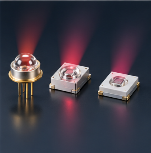
Silicon responsivity peaks in the visible and near infrared and falls steeply as the photon energy drops. A 1050nm emitter can still be read by a good silicon detector, but the margin is thin and it shrinks with temperature and with any optical loss in front of the detector.
At 1200nm a silicon detector is no longer a design choice, and InGaAs or germanium becomes the practical route. From 1500nm upward, InGaAs is the default for most instrumentation because of its noise and speed characteristics.
Detector response is also a system specification, not only a component one. The responsivity curve, the active area, the package window and the amplifier bandwidth together decide whether a given emitter can close the link, and the smallest of those margins governs the result.
Reading those curves together is an IR LED system design task rather than a component comparison, because infrared emitter design choices such as package, lens and drive current all move the operating point along the detector curve. The IR Wavelength & Application Selection stage exists to hold that comparison in one place before a part number is fixed.
Optical Materials and Window Choices Beyond 1000nm
Window transmission becomes a real design parameter above 1000nm. Borosilicate glass is usable into the short wave infrared, quartz extends further, and sapphire combines wide transmission with hardness, while ordinary acrylic and polycarbonate become lossy as wavelength increases.
Coatings matter as much as the substrate. An anti-reflective coating optimised for the visible band can increase reflection at 1650nm rather than reduce it, and a coating specified for the wrong band is worse than no coating at all.
Where the emitter sits behind a sealed window, the design also has to account for condensation and contamination, because a thin film that is harmless in the visible band can scatter a measurable share of a short wave infrared beam. The material and coating decisions belong in the same review as the mechanical sealing decision.
Power Budget: Why Output Has to Be Recalculated
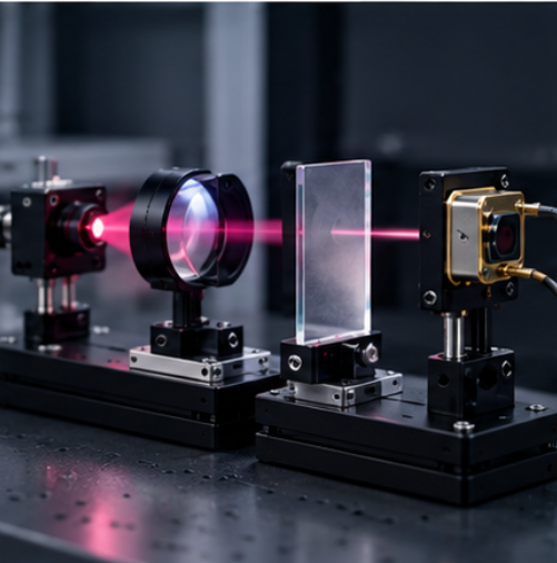
Radiant intensity at the emitter is only the first term. The link budget multiplies window transmission, geometry, target reflectance and detector responsivity, and above 1000nm at least two of those terms are usually worse than the near infrared case.
A practical approach is to write the budget down in milliwatts before choosing a part. Start from the emitter's radiant intensity at the intended drive current, apply the window and optic transmission at the actual wavelength, apply the inverse square loss for the working distance and the target reflectance, then compare the result with the detector's noise equivalent power.
This is also where the drive decision gets made. Pushing current higher raises output, but junction temperature rises with it, and the wavelength shift that follows can move the emission away from the detector peak. Our article on high power IR LED selection and thermal design covers the thermal side, while IR LED radiant intensity explained sets out how the output figure should be read in the first place.
Selection Table: Matching Wavelength to Detector and Task
The useful question is not which wavelength is best but which combination of emitter, detector and window closes the task with margin. The table below is a starting point, not a specification.
| Emitter band | Practical detector | Window material to consider | Typical design note |
|---|---|---|---|
| Around 1050nm | Silicon, near its limit | Standard glass or acrylic | Cheapest detector route, but little margin for loss or temperature drift |
| Around 1200nm | InGaAs or germanium | Borosilicate glass | Leaves the visible-red glow behind and still suits low-cost optics |
| Around 1650nm | InGaAs | Quartz or sapphire | Strong choice where ambient visible light and moisture absorption help the measurement |
| Around 1900nm | Extended InGaAs | Sapphire or specialised IR glass | Water absorption is strong here, which suits moisture-related sensing |
HOUKEM's confirmed IR capability includes 1650nm, 1750nm and 1900nm, with capability extending up to 1900nm for applicable model or project configurations. Availability of a specific wavelength, power and package combination is project specific, so it should be confirmed against the actual requirement rather than assumed from the range.
Applications that already use near infrared emitters are a useful reference point for what changes. The 850nm versus 940nm comparison for industrial sensing shows how much of that decision rests on detector response and ambient light, and the same reasoning simply moves to different materials above 1000nm.
Where a shorter wavelength is still under consideration, 940nm versus 980nm IR LED is the closest published comparison and marks the boundary of the silicon-friendly region.
Validation Checklist Before Production
Validate at the wavelength and drive current that production will use, with the window and optics that production will fit. A bench result taken without the window is not evidence about the product.
Measure the received signal at the extremes of the working distance, at the lowest and highest expected ambient temperature, and after a warm-up period long enough for the emitter to reach thermal equilibrium. Record the margin at each condition rather than a single pass or fail.
Then confirm the detector side. Dark current, bias and amplifier bandwidth all shift with temperature, and a link that closes at room temperature with a laboratory amplifier may not close with the production front end. Our guide to how to measure IR LED output describes the measurement setup that makes these numbers comparable between suppliers.
Frequently Asked Questions
How to evaluate IR LED above 1000nm for an OEM design?
Start from the detector, not the emitter, because the detector material decides which wavelengths are usable at all. Then write the optical budget in milliwatts through the real window, distance and target before comparing candidate parts.
Which parameters matter most for IR LED above 1000nm?
Detector responsivity at the emission wavelength, window transmission at that same wavelength and the thermal shift of the emitter peak matter most. Radiant intensity and forward voltage only become meaningful once those three are fixed.
How does IR LED above 1000nm affect LED performance?
The emitter itself behaves similarly to a near infrared part, but its output is read by a different detector and attenuated by different optics, so the usable signal falls faster with distance. Thermal wavelength shift also matters more, because the detector band is narrower than the emitter drift.
How should engineers validate IR LED above 1000nm before production?
Validate with the production window, the production detector and the production drive current, across the full working distance and temperature range. Record the margin at each condition so a later change in any single element can be judged against a known baseline.
Is an InGaAs detector always required above 1000nm?
No, because a silicon detector can still respond weakly around 1050nm if the optical budget is generous. Above roughly 1100nm, InGaAs or germanium becomes the practical route.
Conclusion: Above 1000nm the Detector Leads the Design
IR LED above 1000nm is not a harder version of the same near infrared design; it is a design where the detector material, the window and the optical budget decide the answer before the emitter is chosen. Once those three are fixed, the emitter selection becomes a short list rather than a search.
If you are specifying an emitter beyond 1000nm and want the wavelength, package and thermal scope checked against your detector and window, send the wavelength and detector scope to the HOUKEM team and we will confirm which configurations apply to your project.
740nm vs 850nm IR LED: Visibility, Detector Response and Application Fit