


UV LED Optical Material Compatibility: Lenses, Windows and Adhesives

Quick Answer: Shorter Wavelengths Narrow the Material Set
Shorter wavelengths carry more photon energy, so they can break chemical bonds in materials that handle visible light without difficulty. The practical effect is that the set of suitable lens, window and adhesive materials shrinks as the wavelength shortens.
Flux density matters alongside wavelength. The same material may survive a low-intensity exposure for years and degrade within weeks under a concentrated beam, so compatibility is always a question of wavelength and dose together.
Why UV Degrades Optical Materials
Degradation usually begins at the surface that receives the light and moves inward. Organic materials absorb part of the emission, and the absorbed energy drives chemical change that shows up first as a colour shift and later as reduced transmission.
The consequences are cumulative rather than abrupt. Transmission falls, the remaining output is redistributed toward longer wavelengths, and the system slowly drifts away from the process window it was qualified against.
Mechanical effects follow the optical ones. A degrading adhesive can lose adhesion before it loses transmission, which is the more serious failure because it changes the geometry of the optical stack as well as its output.
Only curing and detection applications are in scope here. Any claim about sterilising or treating a surface requires dose validation and regulatory evidence that lies well outside a material selection question.
Choosing a Lens, Window and Adhesive
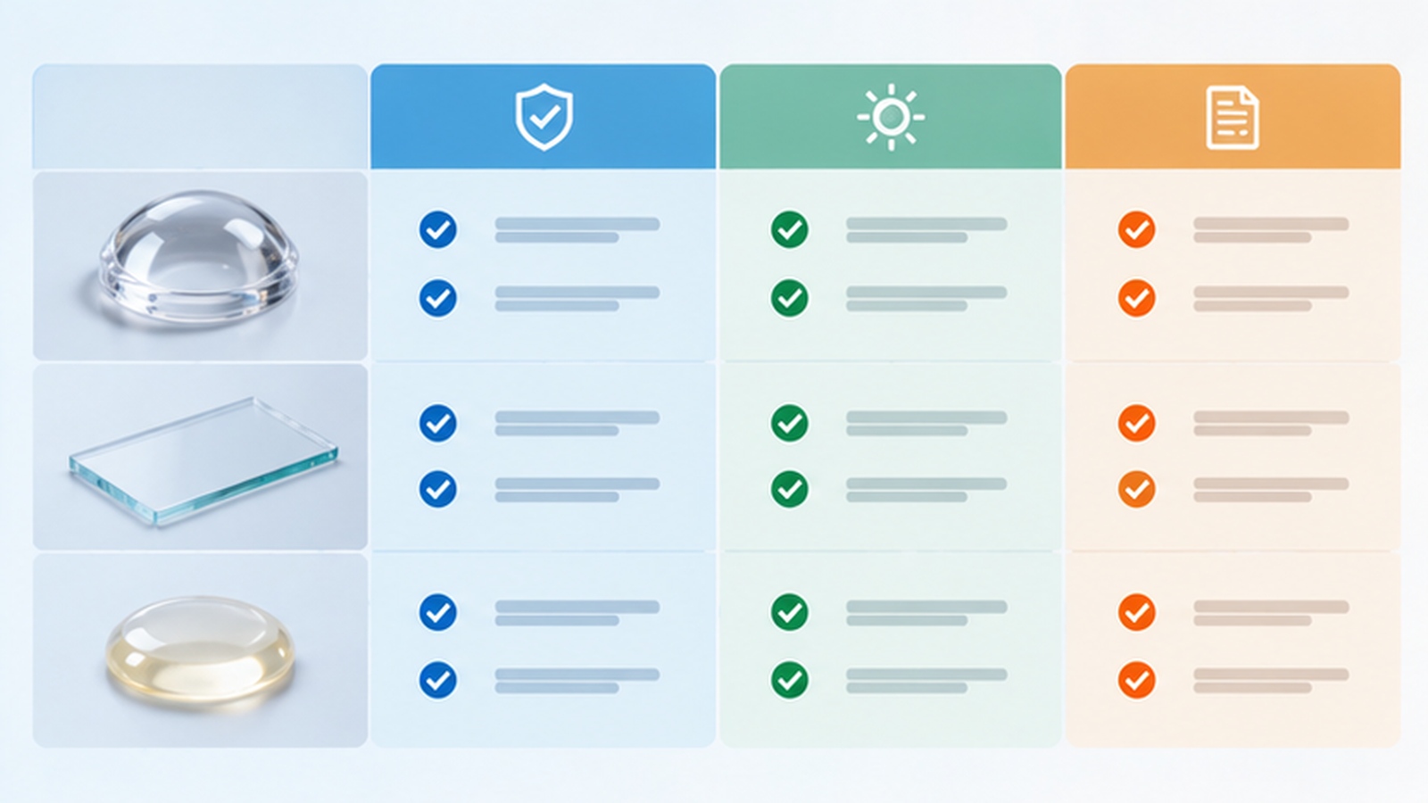
The stack should be reviewed position by position, because each position sees a different flux and has a different job. The table below lists the properties worth checking at each one.
| Stack position | Properties to check | Main risk | Qualification evidence |
|---|---|---|---|
| Primary lens or dome | Transmission at the working wavelength, index stability, thermal tolerance | Yellowing and transmission loss at the hottest point | Exposure test with transmission measured before and after |
| Protective window | Transmission, surface hardness, cleanliness behaviour | Hazing and contamination that diffuse the beam | Transmission measurement plus a cleaning-cycle check |
| Optical adhesive | Transmission, adhesion to both interfaces, elastic behaviour | Adhesion loss before any visible colour change | Exposure plus mechanical check on the bonded joint |
| Reflector or coating | Spectral reflectance, adhesion of the coating layer | Reflectance drop and coating lift-off | Reflectance measurement before and after exposure |
| Sealing and housing interface | Compatibility with the adhesive, thermal expansion match | Seal failure that admits contamination | Assembly-level exposure test with inspection |
The available wavelength and package options are catalogued on the UV LED product range page, and the material choice follows from the band and the power level the project selects.
Two positions deserve particular attention in a high-power design. The primary lens sits closest to the emitter and therefore sees the highest flux and the highest temperature at the same time, and the adhesive is the only material whose failure changes the geometry of the stack rather than only its output.
Heat and UV stress arrive together in that region, which is why the thermal design and the optical design cannot be evaluated separately. Our review of high-power UV LED cooling covers how the thermal path is sized, and the optical materials have to tolerate the temperatures that path allows at the emitter.
Working Distance and Flux Density Make It Worse
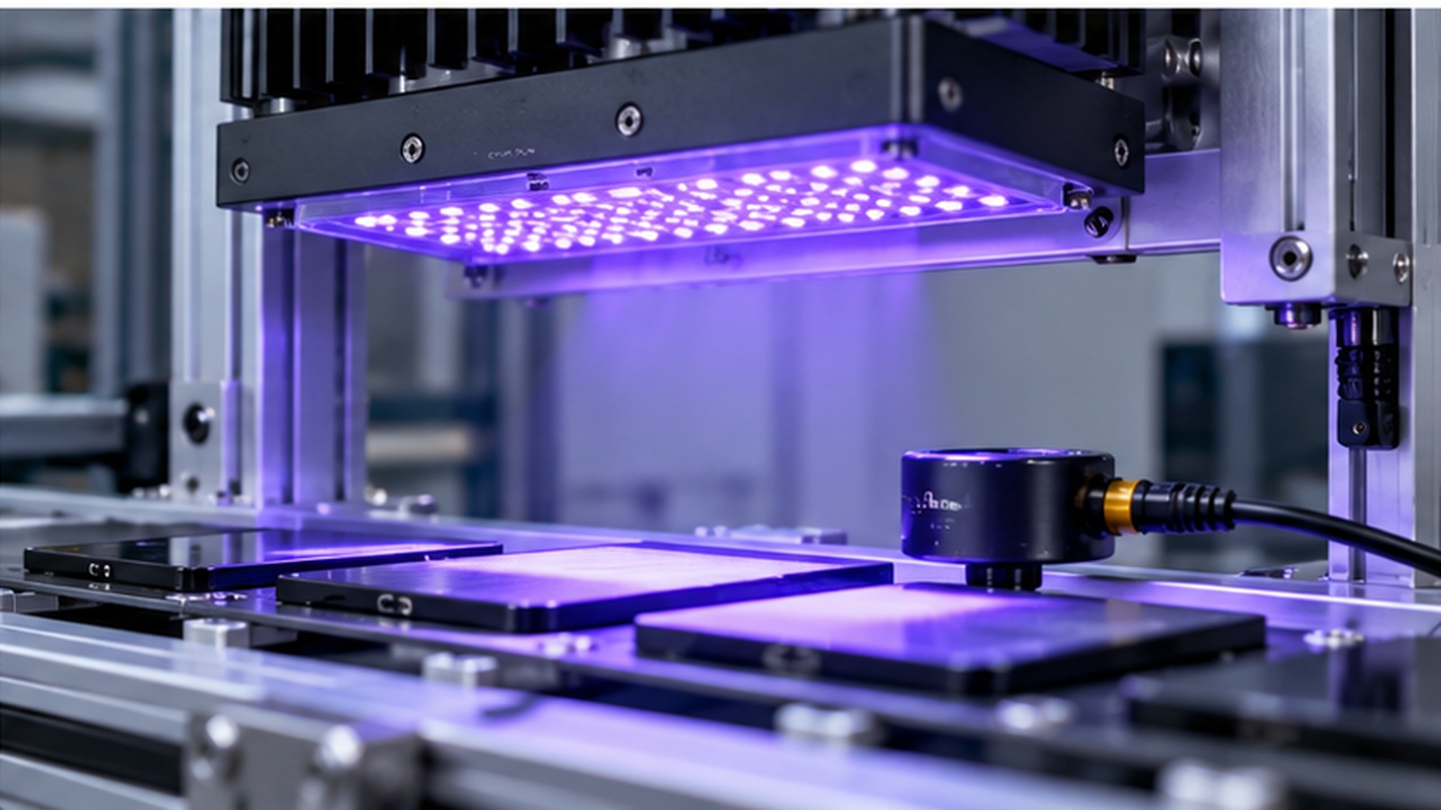
Flux density at the optical surface depends on the geometry of the system. A short working distance concentrates the emission, which raises the dose on the first material in the stack even though the total output has not changed.
Designs that reduce working distance to gain irradiance at the target therefore pay for it upstream. The gain at the workpiece is real, but the exposure seen by the lens and the window rises at the same time.
This is one of the reasons the optical stack and the mechanical layout are best chosen together. Our article on UV LED curing applications describes how the working plane is defined for a curing process, and that definition sets the minimum separation the first optical material has to survive.
UV process engineering normally defines the irradiance the process needs and the tolerance it can accept, while the optical stack decides how close the emitter may sit. UV System Geometry & Optical Design is where those two requirements meet, because the geometry sets the flux on the first material and the material set limits the geometry that remains usable.
Qualifying the Stack Before Production
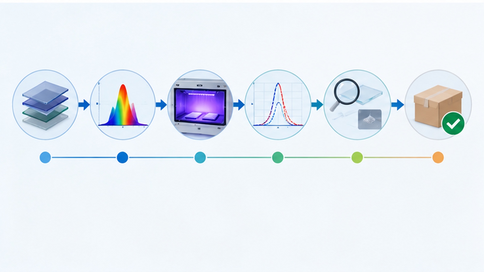
Qualification should start with a short candidate list rather than a single material, because the first choice often fails the exposure test for a reason that was not visible in the datasheet. Measure transmission on each candidate, expose it under conditions that represent the worst case, then re-measure.
The exposure test has to reproduce the flux and the temperature of the real position, not a convenient bench setting. A material qualified at a comfortable temperature can fail in a stack where it sits next to the emitter.
Acceptance should include both optical and mechanical results. A transmission figure that holds while the bonded joint weakens is not a pass, and the mechanical check is the one that catches it. Our guide to how to measure UV LED optical power covers the measurement setup that a before-and-after comparison depends on.
After release, compatibility remains a configuration concern rather than a one-time test. A change of adhesive, coating or window supplier can invalidate the qualification, so the UV LED system design record should name the qualified material at each position and treat a substitution as a change that needs its own review.
Frequently Asked Questions
How to evaluate UV LED optical material compatibility for an OEM design?
Map the optical stack position by position and record the flux and temperature each position sees. Then compare candidate materials against those conditions rather than against a general wavelength rating.
Which parameters matter most for UV LED optical material compatibility?
Wavelength, flux density and the temperature at the material surface matter most, because compatibility changes with all three. Transmission stability and adhesion behaviour are the properties that show whether a candidate holds up.
How does UV LED optical material compatibility affect LED performance?
It affects how much of the emitted output reaches the target as the system ages rather than how much the emitter produces. A degrading lens or window reduces delivered irradiance and shifts the spectrum that arrives at the surface.
How should engineers validate UV LED optical material compatibility before production?
Validate by exposing candidate materials at the real flux and temperature, then re-measuring transmission and checking the bonded joint mechanically. The candidate that passes both checks becomes the qualified material for that stack position.
Does a material rated for UV light always suit a high-power UV LED system?
No, a general UV rating usually describes resistance to a low-intensity exposure. High-power systems combine short wavelengths with concentrated flux, and that combination is what the qualification test has to reproduce before the material is accepted.
Conclusion: Qualify the Stack, Not Just the Emitter
UV LED optical material compatibility decides how much of the emitter output survives to the working plane over the life of the system. Wavelength, flux density and temperature together define the test, and each position in the optical stack deserves its own answer.
Qualify candidates under conditions that match the real position, record the accepted material in the design file, and treat any substitution as a change that needs review. If you are building a UV system and want the optical material requirements confirmed for a specific wavelength and power level, send your application requirements to the HOUKEM team and we will confirm the applicable product scope.
UV LED Leak Detection Fluorescence: Specifying an Inspection Station


