


IR Sensor Crosstalk: Mechanical and Optical Ways to Reduce It

Quick Answer: Remove the Path, Then Adjust the Drive
Crosstalk falls into three route families: light that leaks around the barrier on the sensor face, light that scatters through the medium between the two devices, and light that reflects from the housing or the window inside the assembly. Each one has a different remedy, and none of them is a threshold change.
The order that works is mechanical first, optical second and electrical last. Separation and barriers remove light geometrically; filters and lens choices remove it spectrally or angularly; drive timing only helps when the leakage has a different time signature from the target return.
Stated that way, the design question becomes a question about the physical assembly rather than about the emitter, which is also why crosstalk often appears only after the housing is tooled.
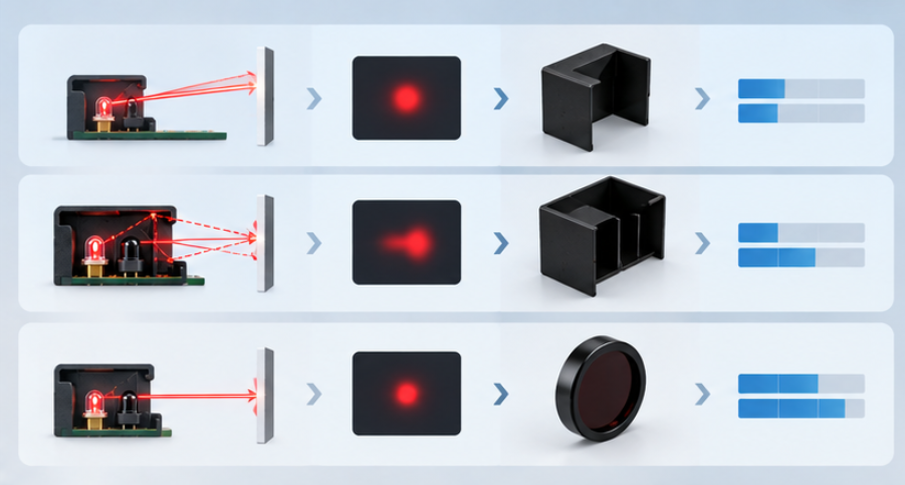
Three Paths Crosstalk Can Take
The table below lists the three routes, what each one looks like from the outside and what removes it. It is ordered by how often each appears in practice.
| Path | Typical symptom | Remedy and trade-off |
|---|---|---|
| Leakage across the sensor face | A permanent presence reading that never clears, insensitive to target position | A raised or recessed barrier between emitter and detector; costs face area and can reduce the usable field |
| Internal reflection inside the housing or window | A reading that changes when the enclosure is pressed or when the window is touched | Matte internal surfaces, a separated window, or a different window material; costs tooling time rather than component cost |
| Scatter through the medium, including dust build-up | A slow drift in reading level over hours or weeks, often worse after cleaning stops | Angular separation or narrower beam emitters; costs sensitivity at the far end of the target range |
The first two paths are in the assembly; the third is in the environment. Separating them is the practical reason to test a sensor head against a strongly absorbing target before fitting it to a machine, because a black target removes the genuine return and leaves only the leakage.
The arrangements used to sense a target are described from the application side in the overview of reflective sensing arrangements, and the route families above apply to each of them with different geometry.
Why Geometry Decides More Than Output
Crosstalk is governed by the small fraction of emitted light that misses the target and still reaches the detector. Increasing emitter output raises the target return and the leakage together, so a brighter emitter commonly makes the problem worse rather than better.
What changes the ratio is the relationship between three distances: the separation between emitter and detector, the aperture through which each one looks, and the sensing distance to the target. Separating the two devices increases the angle at which leakage light must travel, while the target return, which arrives from a known direction, is affected much less.
Angular filtering works on the same principle. A narrow emitter beam and a receiver whose acceptance angle is limited to the expected return direction both suppress leakage arriving from the wrong angle. This is where the emitter choice and the system geometry have to be considered together rather than in sequence, which is the reason the drive and layout are described as one subject in our explanation of the circuit that drives an IR emitter.
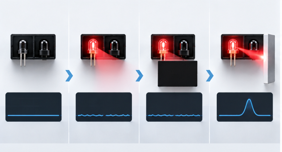
Isolating the Leakage in Four Readings
The sequence below separates leakage from genuine return without special equipment. Each reading removes one candidate and the difference between them is the evidence.
- Read the detector with the emitter off. Any signal here is ambient light or an electrical coupling path rather than optical crosstalk.
- Read with the emitter on and no target fitted. Whatever remains is leakage, since there is nothing to reflect from.
- Repeat with a strongly absorbing target at the sensing distance, for example matt black material. This removes any residual genuine return and leaves the leakage floor.
- Repeat with the real target. The difference between this reading and the previous one is the signal the design has to work with, and it is also the margin available to the decision threshold.
Step three is the one that is usually skipped, and it is the step that turns a complaint into a number. Without it, there is no way to know whether the signal is small, whether the leakage is large, or both.
The measurement side of the same problem follows the reporting discipline used for emitter output, because a reading is only comparable when the geometry, the drive and the target are recorded with it. That discipline is set out in our guide to how IR output is measured and reported.
Timing as the Last Resort
Where the mechanical and optical options are already exhausted, drive timing can separate the two contributions. A pulsed emitter with a synchronous receiver, or a scheme that compares a frame with the emitter on against one with it off, removes a leakage component that is stable in time even if it is large in amplitude.
The remedy has limits. It costs a switching stage, it constrains the sampling rate, and it requires the leakage to be steady, which is not true when the leakage path is contaminated over time, as in the scatter row of the table above.
It also interacts with the receiver's own rejection behaviour, because active sensing systems depend on filtering around a modulation frequency to ignore ambient light and slow drift. How that filtering is structured in an active infrared system is described in our overview of how active infrared sensing systems are built. Adding a second modulation scheme on top of that arrangement should be a deliberate choice rather than a late fix.
Verifying the Fix Before Production
Verification has to happen on the assembled unit, because crosstalk is created by the assembly. A head tested on the bench with the housing open will pass and then fail when it is closed.
Run the four readings again on the closed unit at the temperature extremes it will see, since both the emitter output and the leakage path can change with temperature and fit. Then repeat them after the surface treatments the product will receive, including any cleaning operation, because a matte internal surface that is wiped with an incompatible solvent can become reflective.
The final check is against the decision threshold in the firmware. Leakage that stays below the threshold at the beginning of life but rises with contamination will produce a field failure that looks random, so the margin should be measured rather than assumed. That margin is the same quantity a supplier needs in order to confirm an emitter, a package and a barrier geometry, and the IR capability behind those options is described in the IR LED products range for review against the application.
Frequently Asked Questions
What causes problems related to IR sensor crosstalk?
Most cases come from a leakage path in the assembly rather than from the emitter, such as light crossing the sensor face or reflecting from the inside of the housing. Scatter from a contaminated window is the second common source.
How to troubleshoot IR sensor crosstalk in an LED design?
Read the detector with the emitter off, with the emitter on and no target, and with an absorbing target at the sensing distance. The difference between the last two readings is the signal the design actually has.
Which measurements help diagnose IR sensor crosstalk?
Detector amplitude across those three conditions at the sensing distance, repeated at the temperature extremes and after the housing is closed, separates leakage from genuine return. Threshold margin in the firmware is the second measurement that matters.
How to verify the fix for IR sensor crosstalk before production?
Repeat the readings on the closed unit with the intended barrier and window in place, at both temperature extremes and after the cleaning process. Confirm the leakage floor stays well below the decision threshold rather than merely below it.
Does a brighter emitter help with crosstalk?
No, because output raises the leakage and the target return together, and the detector cannot tell them apart. Geometry, barriers and angular filtering change the ratio between the two, which is what the design needs.
Conclusion: Treat Crosstalk as a Mechanical Problem
IR sensor crosstalk is easier to solve once it is recognised as a property of the assembly. Move the devices apart, give the barrier real geometry, and control the internal surfaces, and the leakage floor drops without any change to the emitter.
The same framing keeps IR Sensing System Design, IR LED system design and infrared emitter design decisions reviewable, because the emitter is then chosen against a measured leakage floor and a required margin rather than against a headline output figure. That is what allows a sensor design to survive tooling instead of being reworked after it.
If a reflective or transmissive sensor design needs the emitter, package and angular options checked against the leakage requirement, send the geometry and the sensing conditions through the inquiry page so the configuration can be reviewed against the application.
UV LED Fluorescence Inspection: Wavelength, Filters and Ambient Light


