


UV LED Leak Detection Fluorescence: Specifying an Inspection Station

Quick Answer: Match the Excitation, Then Control the View
The measurement works when the emitter excites the tracer efficiently and the observer sees the emitted light without also seeing the excitation. Both halves have to hold at the same time.
That is why a station can be bright and still fail. A strong emitter at the wrong band excites the tracer weakly, and a strong emitter at the right band can still fail if ambient light or a missing filter washes out the emission.
Specifying the application means turning three requirements into numbers: the excitation band, the irradiance delivered at the part, and the observation condition that separates the emission from the excitation.
How the Detection Chain Works
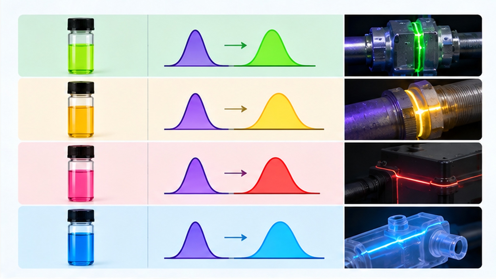
A tracer absorbs UV and re-emits at a longer wavelength, usually in the visible range. The shift between the absorbed and the emitted wavelength is what allows a filter to block the excitation while passing the emission.
The chain has four links: tracer, emitter, optics and observer. Each link has its own requirement, and the weakest link sets the detection limit for the whole station.
A defect becomes visible when the tracer it holds emits enough light to be distinguished from the background. Everything about the station design serves that one comparison.
Matching the Excitation Band to the Tracer
Tracers differ in the band they absorb best, so the emitter choice follows the tracer rather than the other way round. A band that excites one tracer well may excite another poorly, and the difference is visible as a much weaker glow.
| Tracer family | Suitable excitation band | Observation condition |
|---|---|---|
| Long-wave fluorescent tracer | Long-wave UV | Long-pass filter over the camera or the eye |
| General-purpose tracer dye | Long-wave UV | Reduced ambient light with a filter |
| Tracer with visible excitation | Violet to blue range | Band-specific filter and controlled ambient light |
The bands are given as ranges rather than as fixed wavelengths because the useful window depends on the chemistry of the tracer. The bands themselves are described in our overview of UV LED wavelengths and bands, and the category range is listed on the UV LED product family page.
The band matters at both ends of the chain. A band well suited to the tracer also has to be separated from the emission by enough of a gap for a practical filter to work.
Irradiance and Working Distance
What the tracer responds to is the irradiance arriving at the surface, not the emitter output alone. Irradiance falls as the station is moved away from the part, so the working distance is part of the specification rather than a convenience.
This is where a station designed on a bench behaves differently in production. If the same emitter is moved further from the part when it is fitted to a fixture, the delivered irradiance drops and weak defects stop appearing.
The relationship between distance and delivered irradiance is treated in our article on UV LED working distance, and it should be fixed before the fixture is built rather than adjusted afterwards.
Separating the Emission From the Excitation
Detection depends on contrast, and contrast is destroyed by two things: ambient light and stray excitation reaching the observer. Both are handled by the same combination of filter and shielding.
The filter has to pass the emission band while blocking the excitation band. If the two bands are close, the filter becomes expensive or the excitation leaks through, which is a reason to choose a tracer with a wider separation when the application allows it.
Shielding the station from ambient light is the cheaper half of the fix and should be settled before the filter is specified. UV fluorescence inspection as a technique is described in our article on UV LED fluorescence inspection, and the same contrast rules apply there.
A Supplier-Ready Specification Sheet
Six fields turn a use case into an emitter specification, and all six should be sent to the supplier together.
- The tracer or dye in use, with the excitation band that suits it.
- The irradiance required at the part surface, and the tolerance around it.
- The working distance from the emitter face to the part.
- The area that has to be covered uniformly at that distance.
- The observation method, including the filter and the ambient-light limit.
- The acceptance example, ideally a reference sample that must be detected.
The last field is the one that converts the specification into something verifiable. A reference sample with a known defect lets both sides agree on what detection means, instead of arguing over visibility at the end of a build.
Frequently Asked Questions
How to specify UV LED leak detection fluorescence for an OEM application?
Specify the excitation band from the tracer, the irradiance required at the part surface and the working distance to that surface. Add the covered area and the observation condition, and the emitter requirement becomes complete.
Which parameters matter most for UV LED leak detection fluorescence?
The excitation band relative to the tracer, the irradiance delivered at the part and the filter that separates the emission from the excitation matter most. Ambient light control follows closely behind.
How to validate UV LED leak detection fluorescence in the final product?
Use a reference sample with a known defect and confirm it is detected under production conditions, including the real working distance and ambient light. Repeat the check at the longest and shortest working distance the fixture allows.
What should engineers send a supplier for UV LED leak detection fluorescence?
Send the tracer type, the required irradiance, the working distance, the area to be covered, the observation method and a reference acceptance sample. Those six inputs are enough to select an emitter without guessing.
Is brighter always better for this application?
No, because above a point the excitation begins to wash out the emission and the defect becomes harder to see. UV process engineering balances irradiance against contrast rather than maximizing it.
Conclusion: Specify the Chain, Not Just the Emitter
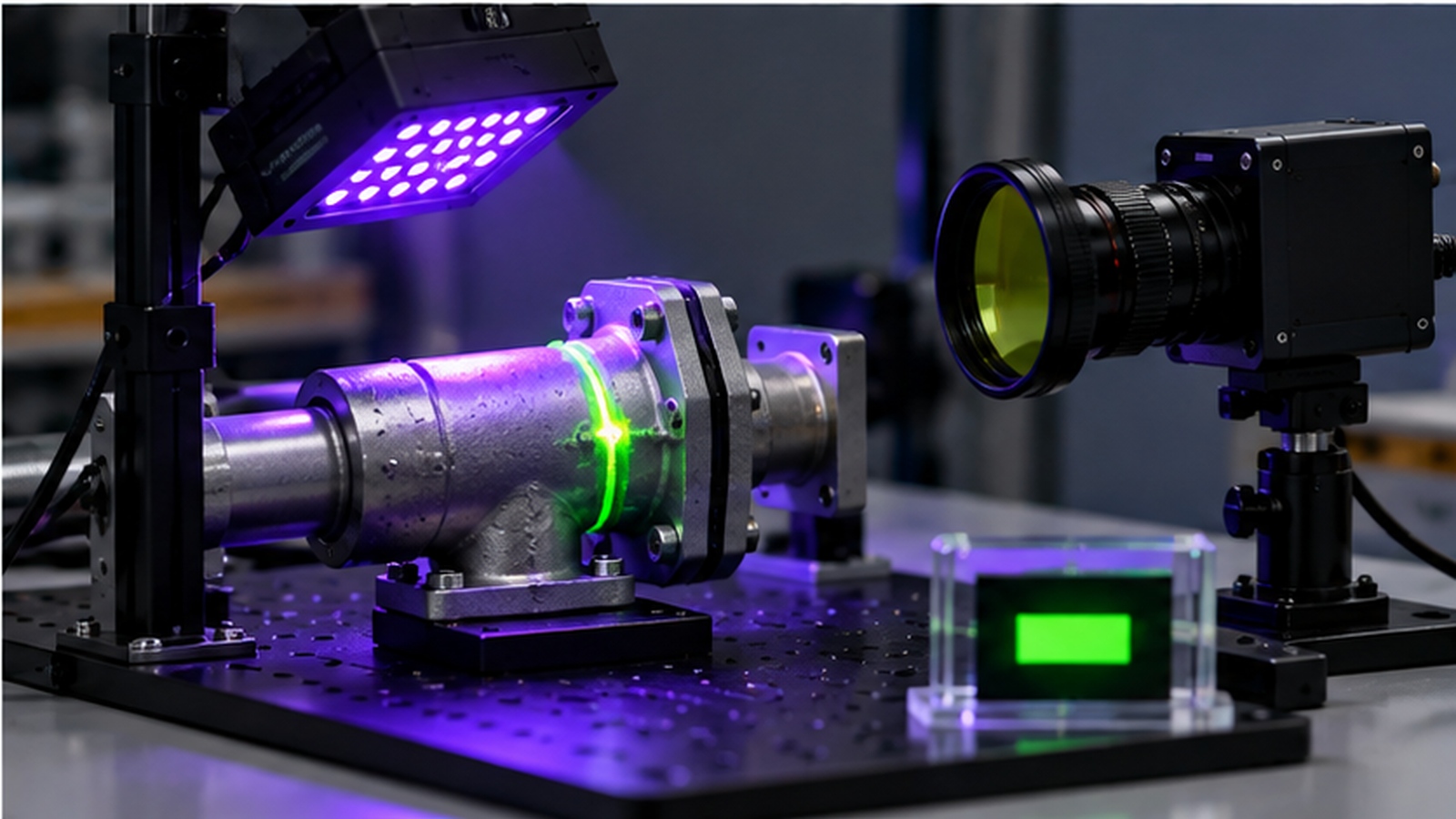
UV LED leak detection fluorescence is decided by a chain of four links, and the emitter is only one of them. Match the excitation band to the tracer, deliver a known irradiance at a fixed working distance and separate the emission with a filter.
Written that way, UV LED system design becomes a set of numbers a supplier can work from, and UV Industrial Applications gain a station that behaves the same on the bench and in production. The reference sample is what keeps the agreement verifiable.
If an inspection station is missing weak defects and the cause is not yet clear, send the tracer type, the working distance and the observation method through the inquiry page so the engineering team can review the configuration.
IR Sensor Crosstalk: Mechanical and Optical Ways to Reduce It


