High Power IR LED: Selection, Drive Current and Thermal Design
What Makes an IR LED High Power
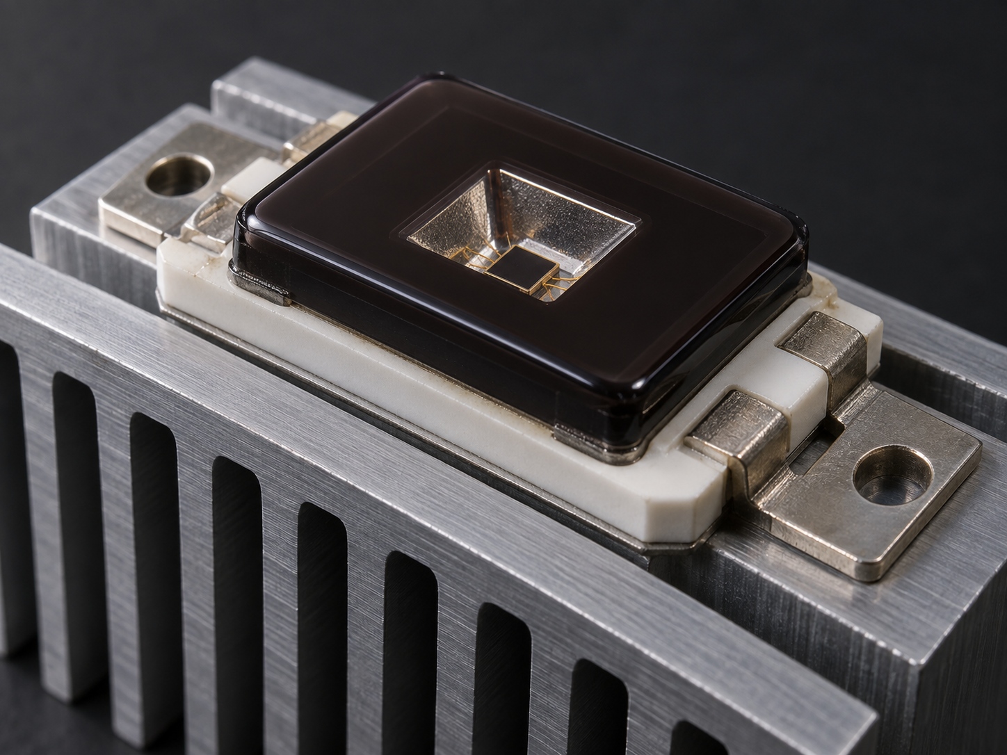
The distinction is practical rather than formal. A standard IR LED is designed to be driven at tens of milliamps from a series resistor and to dissipate a fraction of a watt. A high power part is built to conduct heat out of the die through a slug or substrate, is driven at hundreds of milliamps to several amps, and is expected to be mounted on a heat sink or a metal-core board rather than left in air. In supplier documentation the same device is often listed as a high power infrared LED, and both terms describe the same class of emitter.
Capability ranges also widen at the top end. Confirmed infrared capability at HOUKEM includes wavelengths up to 1900 nm for applicable project configurations, so the first question is not whether a long wavelength exists but which package and drive arrangement delivers it at the output your system needs. That is a project-level answer, not a catalogue answer, because wavelength, power and package combine model by model.
Start From the Optical Requirement
Selection should begin with what the detector or target actually needs, expressed as irradiance at the working distance or as a radiant intensity value. Jumping straight to a wattage figure hides the two variables that matter most: the emission angle, which spreads the output over an area, and the wavelength, which has to fall inside the sensitivity band of the receiver.
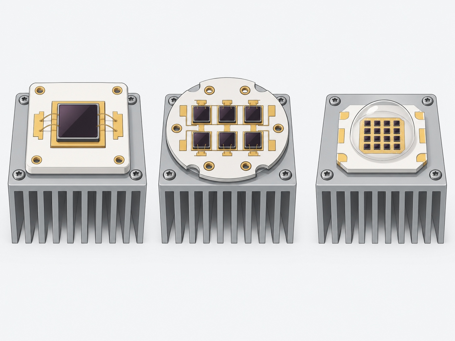
Before comparing packages, convert the optical requirement into a number the supplier can design against, which normally means specifying IR LED radiant intensity at the working distance rather than a bare wattage. Once that number exists, the package choice becomes a consequence rather than a starting point. High-output designs typically fall into three architectures: a single large die, an array of several dies in one package, and a chip-on-board arrangement that packs more emitting area into the same footprint.
Each architecture trades emitting area against thermal spreading and optical control. A single die is easiest to model and to collimate, an array raises output while sharing one thermal interface, and a dense board-level arrangement maximises emitting area but makes current sharing between dies the design problem to solve.
Drive Current, Duty Cycle and Pulsed Operation
The IR LED drive current you set is the primary output control, and it interacts with everything else in the design. A high power emitter should never be driven from a resistor guess, and the guide to choosing an LED driver for UV and IR LEDs covers the constant-current decisions this article assumes. What matters here is that the current you can actually use is set by the thermal path and by how long the emitter stays on.
Pulsed operation is the normal way to raise peak output without raising average dissipation. Many sensing and illumination applications drive the emitter in short pulses at a duty cycle of a few percent, which allows instantaneous current well above the continuous rating while the average junction temperature stays low. When you specify a pulsed application, state the peak current, the pulse width, the duty cycle and the repetition rate, because the safe combination is a joint property of all four rather than a single peak-current figure.
Average dissipation still has to be respected even in pulsed use, and the datasheet limits that apply are the continuous ones once the duty cycle and thermal time constants are taken into account.
Thermal Design Is the Real Constraint
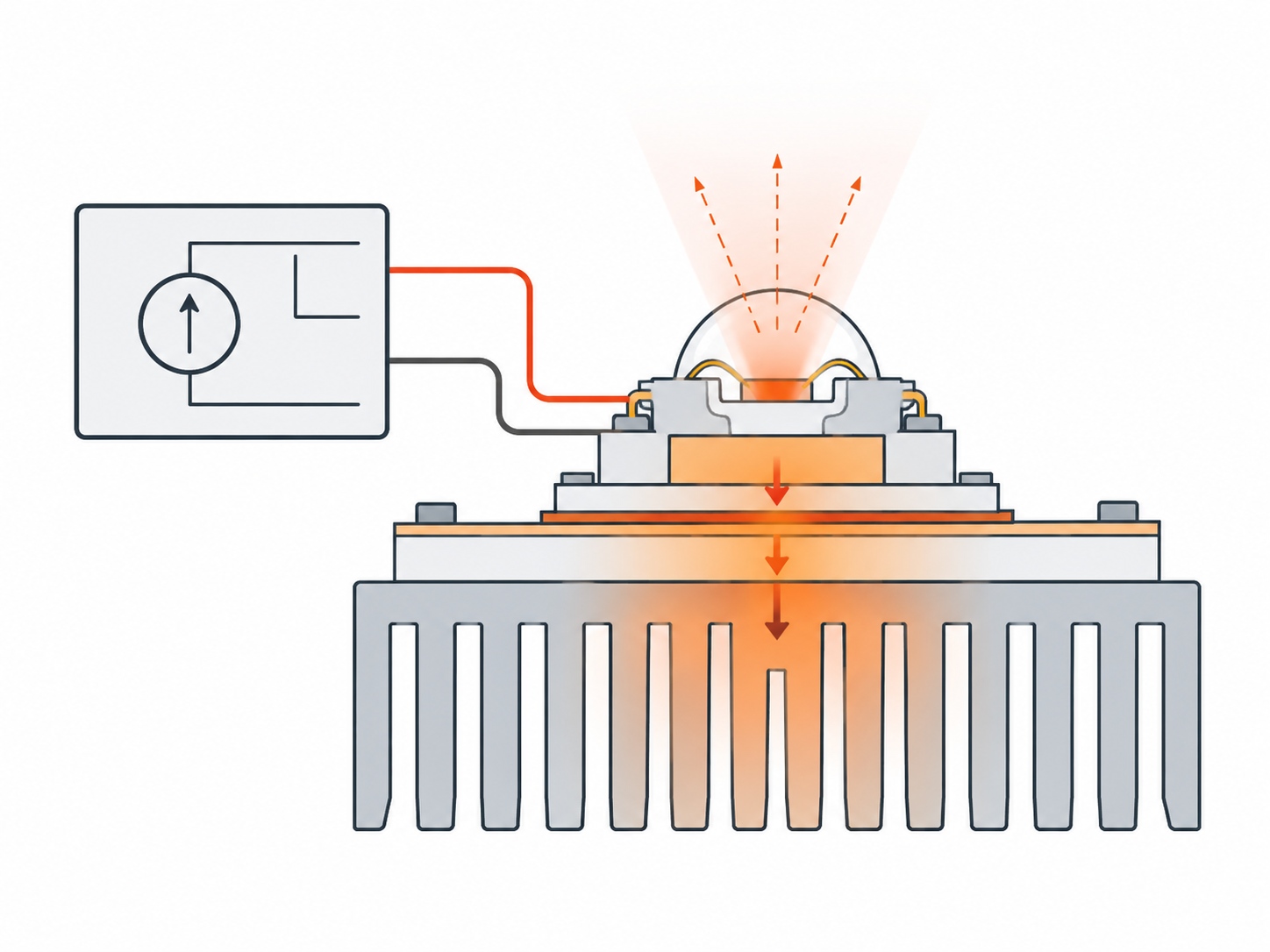
In practice, output is limited by heat before it is limited by the die. The chain from junction to ambient is what limits continuous power, and the published explanation of LED thermal resistance shows how to read RθJA and RθJC without confusing the two. For a high power emitter the difference matters more than in an indicator, because the slug or substrate is designed to be attached to something that can move the heat away. Treating high power IR LED thermal design as a first-order requirement rather than an afterthought is what keeps the optical target reachable.
Three thermal decisions dominate the outcome. First, the interface: a metal-core board or a properly mounted heat sink replaces still air, which is the worst possible sink for a multi-watt part. Second, the spreading: heat that leaves the die but has nowhere to go raises the local board temperature and degrades everything near the emitter. Third, the environment: an enclosed housing with no airflow behaves very differently from the open bench where the first sample was measured. That is why high power IR LED cooling requirements belong in the mechanical design review rather than in the emitter datasheet alone.
Junction temperature also moves the emission itself. As the junction warms, the peak wavelength shifts and the output falls, which in a sensing application can silently move the emitter off the receiver's sensitivity band. This is why the thermal budget is an optical requirement in disguise, and why a design that looks fine electrically can still miss its performance target.
Specifications to Confirm With Your Supplier
Most failed high-power projects trace back to details that were never stated. The high power IR LED specifications below decide whether the first sample behaves like the datasheet.
- Peak wavelength and its tolerance, matched to the receiver's sensitivity band.
- Radiant intensity or irradiance target at the working distance, not a bare wattage.
- Emission angle, and whether a lens or reflector is part of the package.
- Continuous forward current and the high power IR LED forward voltage at the intended operating point.
- Pulse ratings: peak current, pulse width, duty cycle and repetition rate.
- Thermal resistance values and the recommended mounting surface.
- Operating temperature range for the real enclosure, not the test bench.
- Expected output behaviour with junction temperature, so the drive can compensate.
Where the requirement sits outside the standard range, capability ceilings should be read as capability rather than stock. HOUKEM can support high-power LED solutions up to 1600 W for applicable model and project configurations, and confirmed IR capability extends to 1900 nm, but every wavelength-power-package combination is confirmed per project against an approved specification. Minimum order quantity and lead time are likewise model and project based, so request figures for your configuration rather than assuming a general number. HOUKEM provides a two-year warranty across its full product range, with normal warranty terms and exclusions applying.
Applications That Justify High Power
High output earns its cost wherever distance, ambient light or exposure time would otherwise defeat a standard emitter. Long-range illumination, outdoor sensing through glass or grime, and inspection systems that must freeze motion in a single short exposure all sit in this category.
Where a single emitter is not enough, high-power IR LED chips arranged as an array give the radiant density that machine-vision illumination and industrial sensing demand. Most high power IR LED for machine vision projects follow that pattern, with short exposures and fixed ambient light. Arrays also spread the heat across a larger interface, which can be the difference between a stable design and one that drifts with temperature. The trade-off is drive complexity, because current sharing between dies has to be designed rather than assumed.
Applications should stay within the established boundaries for infrared emitters: illumination, sensing and optical detection. Anything that touches biological or medical effect is a different regulatory domain and needs its own evidence, so it is kept outside technical selection discussions like this one.
Conclusion
Selecting the right emitter is an exercise in constraint ordering: the optical target defines the package, the package defines the thermal interface, and the thermal interface defines how much current you may actually use. Work in that order, state pulse and duty-cycle numbers explicitly, and treat every power and wavelength ceiling as a project-level confirmation rather than a catalogue promise.
If you are sizing a high power IR LED and want the electrical and thermal limits checked against your duty cycle, send your requirements and the engineering team will respond with the configurations that fit your project.

Frequently Asked Questions
What current can a high power IR LED take?
The continuous rating is set by the thermal path, not by the die alone, so the safe value depends on how the package is mounted. Pulsed ratings allow higher peak current, but the peak current, pulse width, duty cycle and repetition rate must be evaluated together.
Does a higher drive current always mean more range?
Output rises with current until junction temperature starts to reduce efficiency and shift the wavelength, after which extra current adds heat rather than useful output. Range therefore depends on optics and thermal design as much as on current.
Why does my high power IR LED lose output in the enclosure?
Enclosed housings trap heat, and rising junction temperature reduces output and shifts the peak wavelength. The fix is usually a better thermal interface or more spreading area, not a higher drive current.
Which wavelength should I choose for a high power application?
Start from the receiver's sensitivity band and any material or filter constraints, then confirm the wavelength is available at the power you need, because availability is confirmed per project at longer wavelengths. Capability extends to 1900 nm for applicable project configurations.
Can high power IR LEDs be customised?
Yes, wavelength, package and power configurations can be evaluated for specific projects. Any custom combination is confirmed against an approved specification rather than assumed from a standard range.
UVA LED Wavelength Stability: Why Peaks Drift and How to Specify It
IR LED Radiant Intensity Explained for Engineers