UV LED Power Supply Sizing: Current, Voltage Budget and Headroom
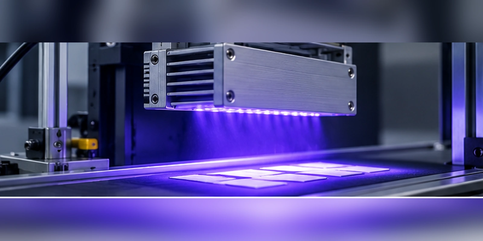
This guide sets out how to size the supply from the array rather than from a wattage label, which parameters drive the decision, and what should be measured before the design is released.
Quick Answer: Size the Current First, the Voltage Second
The current requirement is set by the emitters. A UV array is driven in groups whose current is fixed by the emitter specification, so the supply has to deliver that current to every group that can be on at the same time.
The voltage requirement is then built from the forward-voltage stack. Each series group contributes its own forward voltage, and the string with the highest total determines the voltage the driver must regulate at.
Only after both numbers exist is the power level meaningful. Sizing from the label on an existing supply almost always means discovering that the voltage window was never checked against the warm-end forward voltage of the array.
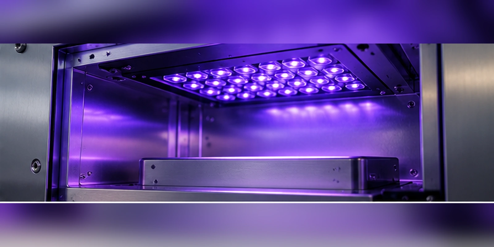
Governing Parameters: Current, Voltage Stack and Duty
The first parameter is the per-group current and the number of groups that can conduct simultaneously. In a continuously driven array that number is the whole array; in a pulsed or scanned array it is the number active in the worst-case phase, which is not always the obvious one.
The second is the forward-voltage stack, evaluated at both ends of the temperature range. Forward voltage falls as the junction warms, so the supply must hold regulation at the cold end where the stack is highest, not only at the steady-state condition.
The third is duty and thermal load. Duty cycle changes the average current the supply must deliver, but it does not change the peak, and the protection and magnetics have to cope with both numbers rather than the average alone.
| Input | What it is derived from | What goes wrong if it is estimated |
|---|---|---|
| Group current | Emitter specification at the declared test condition | Optical output and lifetime both shift |
| Parallel group count | Array layout and worst-case simultaneous conduction | Supply is undersized for the real load |
| Forward-voltage stack | Series count times emitter forward voltage at the cold end | Driver drops out of regulation as the array warms |
| Duty cycle | Process exposure scheme | Thermal and protection sizing is wrong |
| Headroom | Cable drop, driver drop and tolerance | Regulation fails at the worst-case unit |
These inputs feed the drive topology rather than replacing it. The choice between a single string, several parallel branches and a distributed arrangement is covered in our guide to LED driver selection for UV and IR LEDs, and that choice changes how the current and voltage budgets have to be written.
Because the same numbers decide both the drive and the heat load, they sit at the centre of UV Driver & Thermal Design instead of belonging to two separate discussions. A supply selected without reference to the thermal limit will still be asked to deliver current the array cannot safely dissipate.
Headroom: The Number That Is Usually Left Out
Headroom is the voltage the driver needs in reserve to keep regulating. It covers the driver drop itself, the drop along the cabling, and the tolerance on the supply output, and it has to be available at the maximum current the array will ever draw.
The common failure is to size the supply exactly to the cold-end stack. The unit passes on the bench, where cables are short and the array is cold and briefly driven, and then fails in the enclosure where the cable run is longer and the regulation point has moved.
A second failure appears when the array is driven with pulsed current. The peak current during a pulse can be well above the average, so the supply must be able to support the peak even though the thermal design is based on the average.
Because the thermal design and the electrical budget share these numbers, the two are usually settled together. Our article on cooling high-power UV LEDs explains how the thermal path constrains the continuous current the array can actually run at.
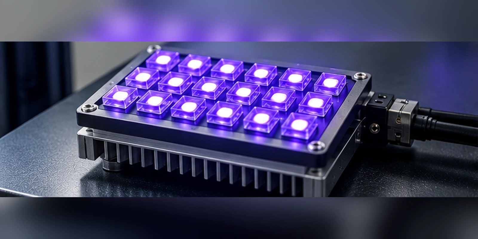
Array Geometry, Duty and Process Coupling
Array layout is not purely optical. The number of emitters that share a supply channel decides both the current per channel and the voltage the channel must reach, so a change in spacing or grouping is also a change to the supply.
Our article on UV LED array spacing covers how emitter pitch and beam overlap shape uniformity, and the same grouping decisions define the electrical channels that the supply has to feed.
The process side then sets the duty. In UV process engineering, a cure recipe that relies on short, high-intensity exposure leaves the array off for most of the cycle, so the supply faces repeated current steps rather than a steady load. That changes the protection and the dynamic response requirement without changing the average power.
Practical projects also keep the emitter choice inside a supportable range. HOUKEM supports UV LED solutions across a top-level range of 255 to 415 nm with high-power platform capability up to 1600 W for applicable configurations, and the exact wavelength and power combination is confirmed per model and project rather than assumed. The current UV LED range is the reference point for that check, because a wavelength that is not supported at the required power changes the array and therefore the supply budget.
Verification and Specification Checklist
Measure the supply output at the array rather than at the supply terminals, with the production cable length fitted and the array at its cold-start condition. The difference between the two measurements is the part of the budget most often missed.
Then run the array to thermal steady state and record the current and voltage again. The shift between the two readings is the evidence that the headroom you allowed is the headroom you actually needed.
Finally, repeat at the lowest supply voltage the product is specified to work from, since a product that only regulates at nominal input is not finished. Record all three measurement sets in the specification so the next revision can be compared against a known baseline, which is also how UV LED system design keeps its process assumptions traceable.
Frequently Asked Questions
How to evaluate UV LED power supply sizing for an OEM design?
Evaluate it from the array outwards: fix the per-group current, count the groups that can conduct together, and build the forward-voltage stack at the cold end of the temperature range. Then add the headroom the driver, cabling and output tolerance require before choosing a supply.
Which parameters matter most for UV LED power supply sizing?
Group current, the cold-end forward-voltage stack and the worst-case simultaneous group count matter most, because together they set the regulation point. Duty cycle and cable length then decide how much of the remaining voltage margin is consumed in practice.
How does UV LED power supply sizing affect LED performance?
It does not change the emitter output when the drive current is correct, but an undersized supply loses regulation and the current then falls below the intended value. The optical result drifts, and the process outcome becomes dependent on the unit rather than on the recipe.
How should engineers validate UV LED power supply sizing before production?
Validate with the production cable length fitted, measuring at the array at cold start, at thermal steady state and at the lowest specified input voltage. The three readings together show whether the headroom in the budget still exists at the worst-case condition.
Can a supply rated above the required wattage be used safely?
A higher power rating does not guarantee the voltage window or the regulation behaviour the array needs. What matters is that the supply can deliver the required current at the highest stack voltage the array presents, with headroom remaining.
Conclusion: Build the Budget Before Choosing the Supply
UV LED power supply sizing is a budget problem: group current, cold-end voltage stack, simultaneous group count and headroom, evaluated before any supply is selected. The measurements that confirm the budget are taken at the array, with production cabling, at both temperature extremes.
If you are building a multi-emitter UV array and want the drive and thermal scope reviewed against your own current and voltage budget, send your array configuration to the HOUKEM team and we will confirm the applicable emitter and module scope.
740nm vs 850nm IR LED: Visibility, Detector Response and Application Fit
IR LED Polar Radiation Pattern: How to Read Angular Intensity Distribution