IR Receiver Sunlight Saturation: Recovering Signal Margin in Bright Conditions
The reflex is to push more current through the emitter. That reflex is expensive and usually wrong, because IR receiver saturation is a limit inside the receiver, not a shortage at the emitter. This guide works from the ambient condition inward: to the receiver operating point, to the optical budget already frozen by the mechanics, to the electrical and timing levers that are still free, and finally to a validation method that predicts field behaviour instead of describing it.
Quick Answer: Why Sunlight Saturates a Receiver Before It Blinds It
A photodiode does not care which photon it converts. Daylight is a broad continuum that fills whatever passband the receiver accepts, so the first stage has to handle the sum of the wanted modulated signal and the unwanted background. When the background alone pushes the transimpedance stage or the comparator input close to a rail, the gain available for the modulated component collapses, and the output stops reporting the emitter at all.
Nothing has been damaged and nothing was under-driven. The dynamic range of the receiver has simply been spent on an input the design never intended to accept, and the recovery is a matter of restoring headroom rather than adding power.
From Ambient Irradiance to Receiver Operating Point
The useful way to model this is a chain, not a single number. Ambient irradiance arrives at the product window, part of it is attenuated by the window material and coating, the remainder reaches the detector, and the detector converts it into a DC photocurrent. That current shifts the operating point of the amplifier and, in receivers with automatic gain control or an adaptive threshold, it also changes the decision level used to declare a detection.
Two consequences follow. First, the failure is a function of the whole optical stack, so a receiver that saturates behind one window may behave behind another. Second, the receiver's own response time lengthens as the background grows, because the amplifier is working closer to its limit; slow recovery after a bright event is often the first measurable sign that margin is being consumed.
| Ambient condition | What changes at the receiver | First visible symptom |
|---|---|---|
| Indoor reflected light | Small steady photocurrent, stable threshold | None at rated range |
| Open shade under a bright sky | Large DC level with slow drift as the sky changes | Threshold wanders; range shortens late in the day |
| Direct sun on the window | Near-saturated front end, compressed modulation depth | Output stuck in one state regardless of target |
| Sun plus a reflective surface | Local, angle-dependent saturation | Intermittent dropouts at specific product orientations |
| Modulated lighting or dimmed drivers | In-band interference above the ambient plateau | Chatter and false edges rather than a dead channel |
The table matters because the last row is often misdiagnosed as saturation. A channel that chatters is receiving interference it can filter by modulation; a channel that goes quiet has run out of headroom and needs its operating point moved.
Identifying the Symptom Before Changing Anything
The measurement that separates the cases takes two captures under the same ambient. With the emitter disabled, record the DC level at the receiver output; that value is the background the design must tolerate. With the emitter enabled, record the modulated amplitude on the same scale. The ratio between the two numbers is the only figure that predicts whether the channel will survive the field.
Three signatures are worth recognising on the scope. An output that sits flat against a rail and only moves when the product is shaded is saturated. An output that recovers slowly after the sun is blocked is close to saturation with a long time constant. An output that switches at a rate unrelated to the emitter's modulation is picking up something else entirely, and the methods used to attribute that leakage are set out in the analysis of IR sensor crosstalk, which is a different fault with a different fix.
Recording the two captures in the same units matters as much as taking them. The receiver's output is optical power converted to a voltage or a count, and how that conversion is calibrated decides whether the ratio you compute can be compared with a later measurement. The geometry and reporting conventions for that calibration are covered in how to measure IR LED output.
The Optical Budget Is Usually Already Frozen
By the time a saturation complaint arrives, the window, the filter and the mechanical apertures are in tooling. That constrains the problem in a helpful way: the optical side defines a ceiling, and the electrical side decides how close to that ceiling the product actually operates. If the ceiling itself is too low, no amount of firmware tuning will lift it, and the honest answer is a stack-up change at the next revision.
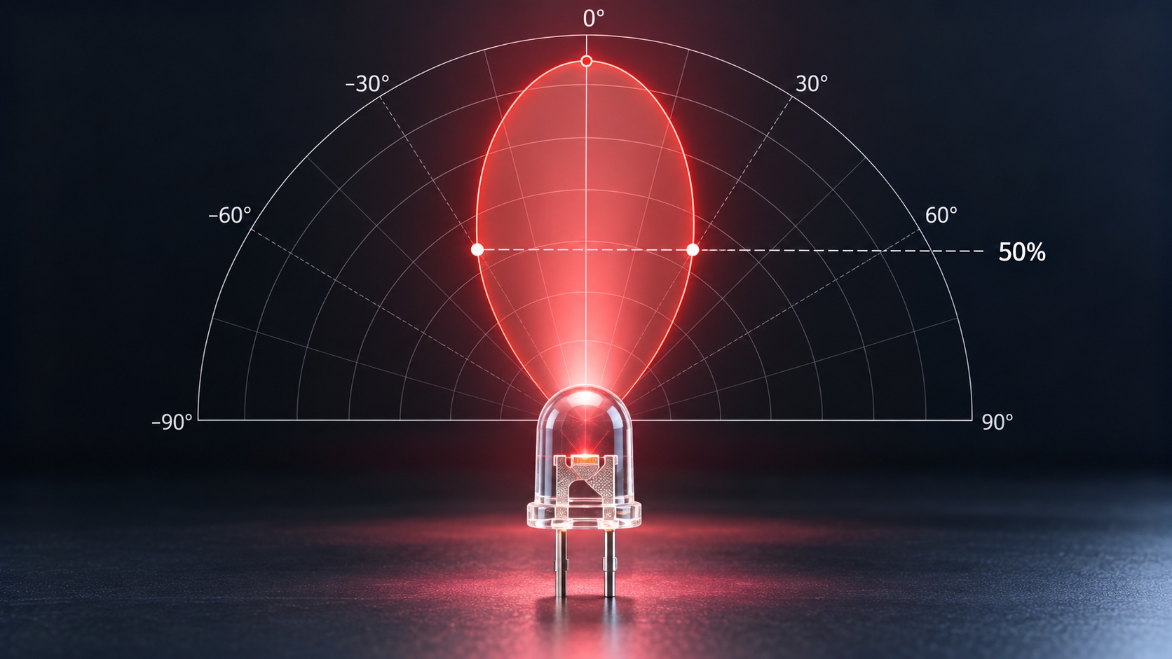
Where the ceiling is adequate, the remaining work is to stop wasting it. A receiver with a wide field of view accepts more background from more directions, and the angular behaviour of the emitter that has to cover that field is described in the guide to IR LED polar radiation pattern. Mismatch between the emitter's beam and the receiver's acceptance is a geometry problem that shows up as margin loss long before it shows up as a dead channel.
Electrical and Timing Levers That Still Work
Once optics are fixed, four levers remain, and they trade against each other rather than stacking freely.
- Front-end gain. Reducing gain lowers the DC level the amplifier must carry and restores headroom, at the cost of weak-signal sensitivity at the far end of the range.
- Detection threshold. Raising the threshold above the ambient plateau removes false detections caused by the background, but it also raises the minimum signal that counts as a target.
- Modulation and synchronous detection. Moving the modulation band above the rate at which daylight varies lets the receiver reject the background by frequency instead of by amplitude. This is the most effective lever when the background is large but slow.
- Receiver on-time. Sampling in short windows instead of continuously reduces the integrated background, at the cost of timing precision.
Every one of these changes the minimum detectable signal. That is why the decision cannot be made on the saturation symptom alone: the acceptance test has to re-check the weak-signal corner after the threshold or gain is moved, otherwise the fix simply relocates the failure to the far end of the specified range.
Why Raising Emitter Power Rarely Helps
When the receiver is limited by ambient rather than by signal, increasing drive current raises the wanted signal and leaves the background exactly where it was, so the amplitude ratio does improve on paper. In practice the gains are small, because the receiver is already compressed: a front end pinned near a rail does not produce proportionally more output for a proportionally larger input. The cost, however, is immediate, since a harder-driven emitter heats, shifts wavelength and loses output over its life.
Most reports of IR sensor sunlight interference arrive as a range complaint rather than a dead channel, which is why the wider class of infrared sensor outdoor interference is so often treated with current instead of with headroom. A sunlight problem that appears only at high ambient temperature is particularly prone to this misdiagnosis, because the temperature rise from extra drive current reproduces the symptom the engineer is trying to remove. Emitter selection still matters, but as a choice of wavelength and beam for the application rather than as a power dial; the trade-offs between the two common sensing wavelengths are summarised in 850nm vs 940nm IR LED for industrial sensing.
An Outdoor Validation Protocol
Field failures come from corners that bench tests never visit. The protocol below walks the corners in an order that finds the cheapest failure first.
- Write the worst ambient case as a number: orientation, time of day, surface in front of the product, and whether direct sun can reach the window.
- Record the receiver output with the emitter disabled at that condition, and record how far it drifts over ten minutes.
- Record the modulated amplitude with the emitter enabled at the same condition, then compute the ratio.
- Repeat the pair at the temperature extremes the product will see, because both the filter band and the emitter output move with temperature.
- Repeat at the edges of the field of view and at the shortest and longest target distance in the specification.
- Repeat once at the minimum supply voltage, where driver headroom is smallest.
The verdict is a ratio, not a waveform. A channel that keeps its ratio at the worst corner is a design; a channel that keeps it only in the lab is a support ticket waiting to be written.
Frequently Asked Questions
Why does an IR sensor fail in sunlight but work in shade?
Because shade removes most of the background photocurrent, so the receiver recovers the headroom that direct sun consumed. The pattern where an IR sensor fails in sunlight and recovers the moment a shadow falls is the clearest evidence that the limit is dynamic range rather than emitter output.
Can I prevent IR receiver saturation outdoors by increasing emitter current?
Only marginally, and only while the receiver still has usable gain left. How to prevent IR receiver saturation outdoors is really a question about threshold, modulation band and gain, so raising drive current treats the symptom that is cheapest to see rather than the cause.
Does a narrower optical filter always improve sunlight rejection?
A narrower passband admits less daylight, which raises the ratio between signal and background, but it also admits less of the emitter's own output and shifts more with angle. Past a point the narrower filter costs more margin than it returns, so bandwidth has to be chosen against a stated ambient condition rather than minimised.
What does saturation look like on an oscilloscope?
The output sits flat against a rail and does not follow the modulation, and it may take an appreciable time to come back when the light source is removed. A DC-coupled capture with the emitter switched off shows the same plateau, which is how the background level is separated from the signal.
Is saturation the same problem as crosstalk?
No. Crosstalk is the emitter's own light reaching the detector by an unintended path and scaling with emitter power, whereas saturation is the detector running out of range because of light that arrives from somewhere else entirely.
How much margin should be left at the worst ambient?
Enough that the ratio still clears the detection threshold at the minimum supply voltage and at both temperature extremes, with the target at its least reflective. If that corner is not measured, the margin that exists is unknown rather than adequate.
Conclusion: Budget the Ratio, Then Protect It
Saturation in bright light is the most common way an otherwise sound infrared channel loses its range. It is also one of the easiest faults to design out, because the numbers that decide it can all be measured before tooling: background level with the emitter off, modulated amplitude with it on, and the ratio between them at the worst corner the product will meet.
Fix the optical ceiling first, then spend the electrical levers deliberately and re-check the weak-signal corner after every move. If you are specifying an emitter and receiver pair for an outdoor product and want the optical budget reviewed against your worst-case ambient, send your project requirements to the HOUKEM team.