IR COB LED: Why High-Power Infrared Emitters Use Chip-on-Board Packaging
What an IR COB LED Actually Is
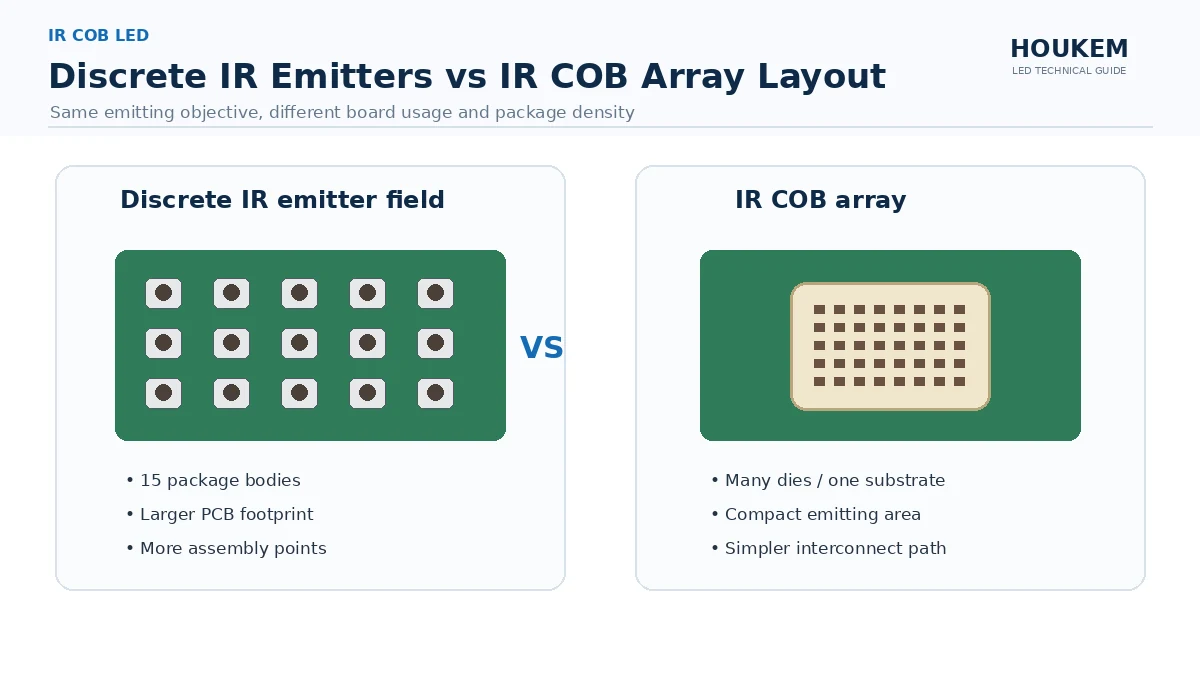
In a chip-on-board architecture, bare infrared emitter dies are mounted directly onto a single substrate and covered as one unit, rather than being sealed individually into discrete packages and then placed on the board. The substrate becomes both the mechanical carrier and the primary thermal path. HOUKEM builds infrared products within its wider infrared LED product family, where confirmed capability extends to 1900nm for applicable projects and the exact wavelength, power and package combination is confirmed per project.
The practical consequence is that the unit of specification shifts. A discrete emitter is specified one part at a time. An IR COB array is specified as one optical and thermal object, which is why the specification conversation starts earlier in the design cycle.
Why High-Power Infrared Emitters Move to Chip-on-Board
When output per unit area has to rise, discrete packaging runs out of room. Each discrete part carries its own package body, its own solder joints and its own share of board area, so packing dozens of them together consumes space that does not emit anything. That is the core reason why are high power infrared leds built as cob rather than as dense fields of discrete parts. High power IR LED packaging decisions then rest on three quantities: how much emitting area fits the available aperture, how the strings are grouped electrically, and how much heat the substrate can move out of the array.
Emitter density and array layout
Removing the individual package bodies lets more emitting area sit inside the same aperture. The design question then becomes how the dies are distributed inside that aperture, because a tight cluster produces a different beam and a different hot spot than a spread layout of the same total area.
Series and parallel grouping
A COB array is wired as a network of series strings, and the grouping determines the required drive voltage and current. Because the dies sit on one substrate, a single failed string affects a visible region, so the grouping choice is also a redundancy decision rather than only an electrical one.
The Thermal Path in an IR COB Array
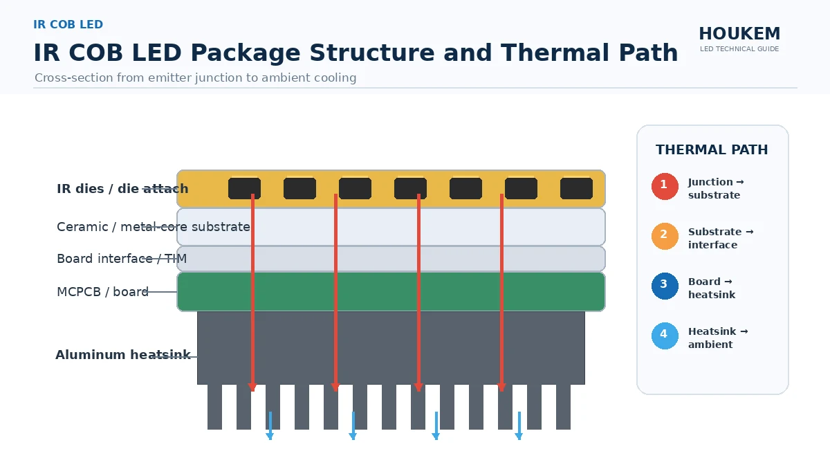
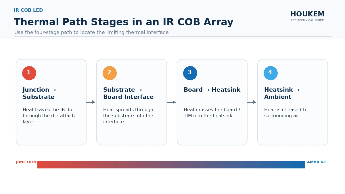
Infrared emitters convert a large share of their input into heat rather than light, so the thermal path is the constraint that decides usable output. In a COB array the junction-to-substrate distance is short by construction, which means the limiting step usually moves outward to the board and the mounting interface. The general behaviour of that chain is set out in LED thermal management fundamentals.
| Stage in the path | What it does | What the buyer must decide |
|---|---|---|
| Junction to substrate | Shortest link in a COB array because dies are mounted directly on the carrier | Accepted as designed; confirm the die-attach method with the supplier |
| Substrate to board interface | Usually the largest single thermal resistance in the stack | Interface material, thickness and controlled mounting pressure |
| Board to heatsink | Spreads heat into the mass that finally rejects it | Whether a metal-core board is required, or FR-4 with a designed thermal path is enough |
| Heatsink to ambient | Sets the steady-state temperature for the chosen duty cycle | Cooling method and enclosure airflow or coolant access |
Substrate selection is where many IR COB projects stall, because a metal-core board solves heat spreading but changes cost, tooling and assembly. The trade-off between a metal-core substrate and a thermally designed FR-4 board is examined in MCPCB versus FR-4 substrate choice, and it applies directly to infrared arrays because they are usually driven harder than visible indication parts.
Beam Shaping and Optics
A COB array emits from a distributed area rather than a point, so a lens designed for a single emitter will not produce the same result. The designer has to choose between treating the array as one extended source and shaping a broad field, or imaging each emitting region separately. A COB package for infrared emitters also moves the aperture decision earlier in the project, because the emitting area is fixed by the substrate rather than by a lens chosen per emitter, and that decision has to be made before the optical aperture is released.
Pairing an IR COB Array with the Rest of the Design
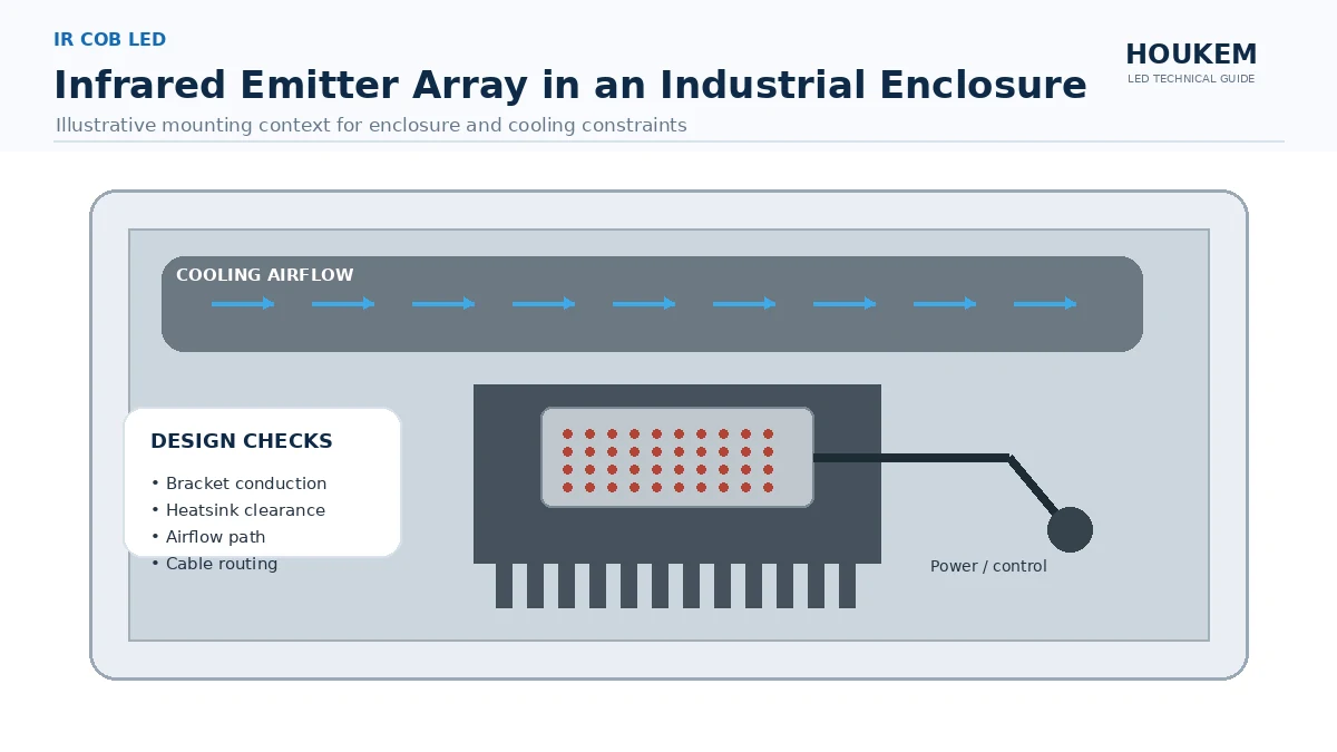
Because the array concentrates output and heat in one place, the surrounding design has to absorb both. The selection logic for drive current, wavelength and thermal design in a high-power infrared system is covered in high-power IR LED selection, and it is worth reading before the array is chosen rather than after.
Two consequences are easy to miss. First, infrared emitter thermal path behaviour differs from visible emitters because the emitted energy does not leave the system as visible light, so almost all input energy has to be managed as heat. Second, because the array is one replaceable unit, a thermal failure is a whole-array replacement rather than a single-part swap, which raises the value of getting the interface right the first time.
Specifying an IR COB LED in an RFQ
An enquiry that states only a wavelength and a power figure cannot be answered precisely. To how to specify an ir cob led array properly, the requirement should cover:
- The target wavelength and the tolerance that is acceptable, plus the measurement condition.
- Total electrical input power, drive current per string and the duty cycle the array must survive.
- The emitting area or aperture size, and the beam pattern the application needs.
- The cooling method available in the enclosure, including whether coolant or forced air is accessible.
- The acceptance test that will be applied to the delivered array, so pass and fail are agreed in advance.
IR cob led thermal management and ir cob led vs smd ir led are the two comparisons that most often decide the architecture. Chip-on-board wins where density, shared thermal base and one optical aperture matter; discrete or SMD infrared emitters win where replacement cost, simple low-power drive or a very small single emitter is the priority.
Frequently Asked Questions
What is an IR COB LED?
A chip-on-board infrared emitter is mounted directly onto one substrate instead of being sealed in a separate discrete package. The emitters share a single thermal base, which is why the architecture suits arrays that must run at high drive power.
Why are high-power IR LED arrays built with COB packaging?
Chip-on-board mounting removes the individual package body between each emitter and the substrate, so heat travels a shorter path. That shorter path is what allows a dense infrared array to hold its output instead of losing it to self-heating.
Is a chip-on-board infrared array better than a through-hole IR LED?
There is no universal answer, because the two architectures solve different problems. A through-hole part is simpler to prototype and replace, while a COB array is chosen when several emitters must share one thermal base and one optical aperture.
What changes in the thermal design when you move to IR COB?
The bottleneck normally moves from the package to the board and the interface between board and heatsink. That means substrate choice, interface material and mounting pressure become the controlling variables rather than the emitter itself.
How should a chip-on-board infrared array be specified in an RFQ?
State the wavelength, the total electrical power or drive current, the emitting area and the duty cycle the array must survive. Add the cooling method and the required output test, because those four items decide whether the requested combination can actually be built.
Does HOUKEM supply IR COB LED arrays?
HOUKEM offers a high-power infrared emitter platform, with confirmed capability extending to 1900nm for applicable projects. The exact wavelength, power and package combination is project-specific, so it should be confirmed against your requirement.
Bringing the Design Together
Chip-on-board packaging changes where the difficulty sits in a design. The emitter itself becomes a single object with a defined aperture and a short internal thermal path, and the hard decisions move to the interface, the substrate and the cooling method. Buyers who plan those three items before freezing the enclosure avoid the common failure of an array that performs on the bench and drifts in the product.
If you are specifying a high-power infrared emitter, share the wavelength, the drive condition, the available cooling and the required output test with the HOUKEM engineering team and send your IR emitter requirement so the applicable configuration can be confirmed against your project.
SMD LED Anode and Cathode: How to Identify Polarity Correctly
MCPCB vs FR4 LED Thermal Design: Choosing the Right Substrate