How to Read an LED Reflow Soldering Profile

Quick Answer: Read the Limits Before the Shape
The profile defines four boundaries: how fast the board may be heated, how long it may sit in the soak region, how hot it may become at the peak, and how long it may remain above the melting point of the alloy. Each boundary protects a different failure mode.
Everything else in the document is a consequence of those four numbers plus the cooling rate. If a proposed profile satisfies the boundaries and the assembly is fully formed, the exact shape between the boundaries is a process choice rather than a requirement.
This is why two boards with the same LED package can legitimately run different profiles. The package limits are shared, but the board changes how quickly heat reaches the joint, and the profile has to compensate for that rather than ignore it.
The Four Zones You Are Actually Reading
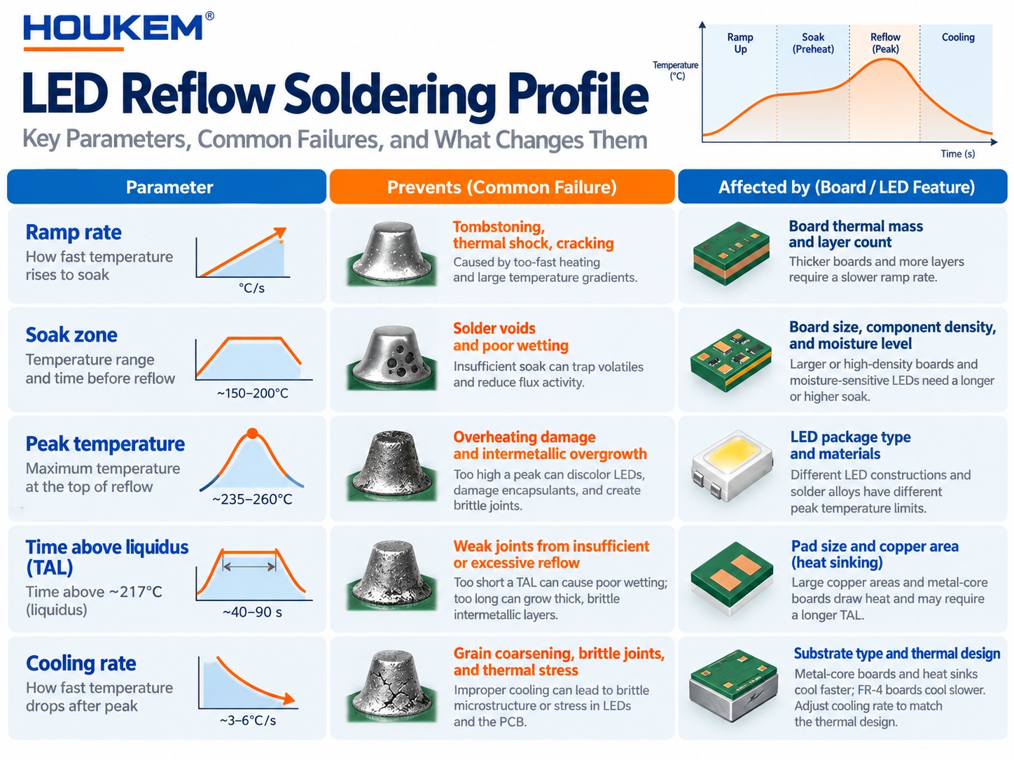
Preheat brings the assembly up from ambient at a controlled rate, and it exists to limit the thermal shock experienced by the package and by the solder paste. The rate matters more than the duration in this region, because a fast ramp distributes stress unevenly across a large board.
The soak region lets the assembly reach a more uniform temperature before the alloy melts, and it also activates the flux. Time here is bounded from both ends: too little and the assembly is not thermally settled, too much and the flux is consumed before the joint forms.
Reflow is the region above the melting point of the alloy, and the quantity that matters is the time spent above that threshold rather than the total time in the furnace. The peak temperature sits inside this region and is the single most consequential number on the page.
Cooling controls the grain structure of the solidified joint and, in practice, the appearance of the finished solder fillet. A cooling rate that is too slow produces a coarse joint, while a rate that is too fast reintroduces the thermal stress the preheat stage was designed to limit.
Parameters That Decide Whether a Profile Fits the Part
The table below sets out the parameters a process engineer reads first, together with the failure each one is intended to prevent. These are the fields to compare when a supplier publishes a recommended profile and the buyer has to decide whether it applies to the actual assembly.
| Parameter | What it controls | What changes it on a real board |
|---|---|---|
| Ramp rate to soak | Thermal shock and flux behaviour | Board thickness, copper area and component density |
| Soak time and temperature | Thermal uniformity before melting | Package mass and the number of thermal vias under the pad |
| Peak temperature | Joint formation and package stress | Package construction and the melting point of the alloy |
| Time above liquidus | Complete melting and wetting | Thermal mass of the assembly and the reflow atmosphere |
| Cooling rate | Joint structure and residual stress | Conveyor design and the thermal mass around the joint |
| Number of passes | Accumulated exposure of the part | Whether the board is processed on one side or two |
Reading the table across rather than down is the useful habit. A parameter without the condition that changes it cannot be translated from a supplier recommendation into a working production profile.
How Board and Package Mass Change the Same Profile
Two assemblies can share an identical LED part number and still require different profiles, because the profile describes the joint rather than the component.
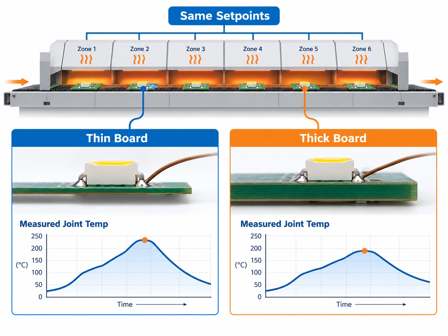
A thick board with large copper planes draws heat away from the joint during reflow, so the measured peak at the joint is lower than the furnace setting. A thin board with a small pad does the opposite. The practical consequence is that the furnace setpoint and the joint condition are two different numbers, and only the second one is compared against the limits in the datasheet.
Package mass compounds the effect. A small surface-mount package reaches the soak condition quickly, while a heavier package with a metal core or a large thermal pad lags behind the rest of the board. Footprint decisions made for electrical or mechanical reasons therefore have a thermal consequence at assembly time, which is one reason land pattern choices are usually settled before the profile is written rather than after. The design considerations behind those footprints are covered in our guide to SMD 7 segment display design.
For high-volume work the correction is made empirically rather than analytically, by measuring the joint temperature on a representative assembly and adjusting the setpoints until the measured curve sits inside the published limits with margin on both sides.
Verifying the Profile Before Production
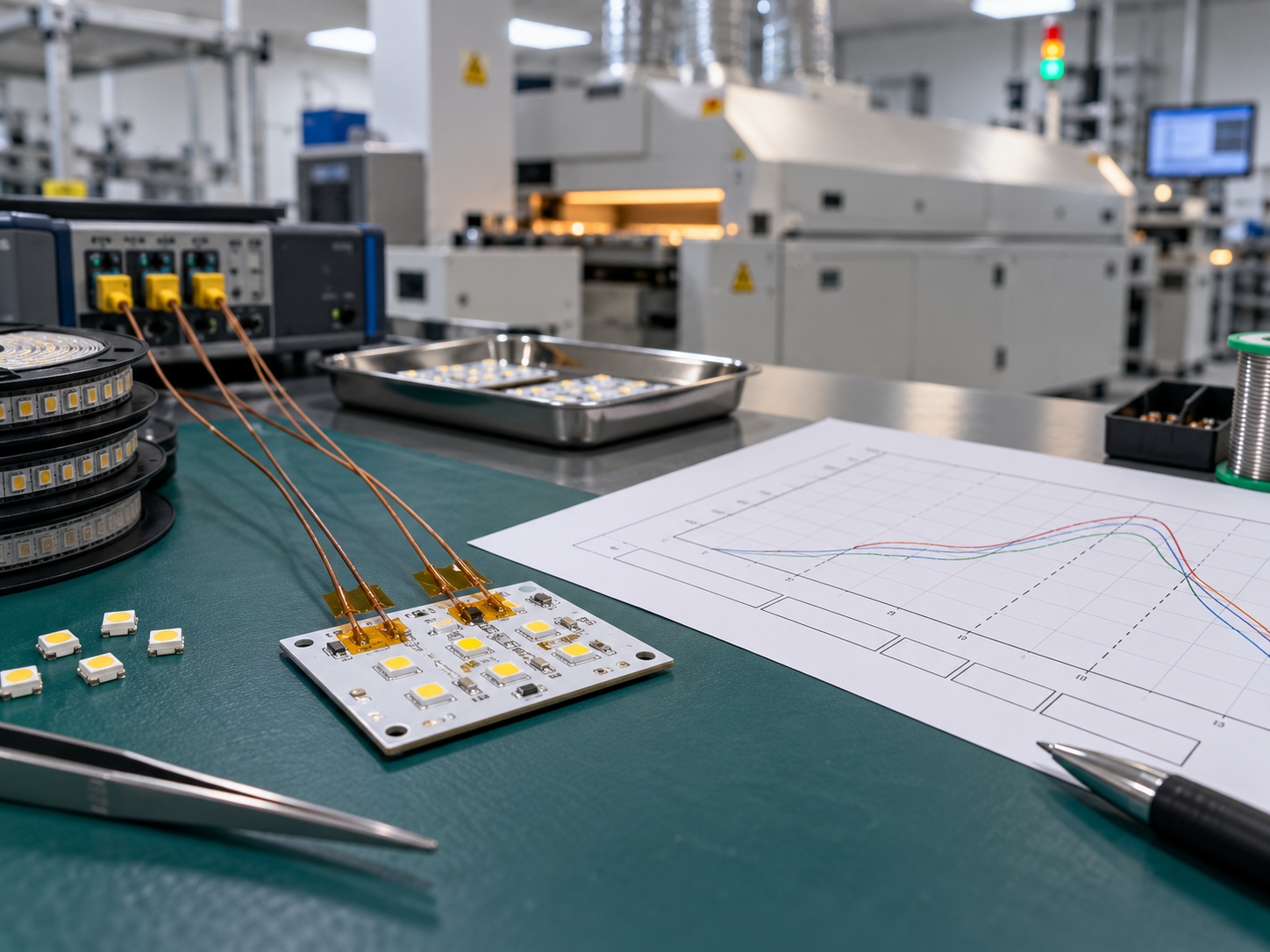
Verification means attaching thermocouples to the assembly where the joint will actually be, running the board through the furnace, and comparing the recorded curve against the limits. A profile copied from a furnace display is not verification, because the display reports the environment rather than the joint.
Two attachments are usually enough for a first run, one on the LED pad and one on the heaviest feature on the board, because the difference between them shows how much the board is distorting the intended curve. If the two traces separate widely, the setpoints need to change before any further work.
Moisture handling has to be resolved before the profile is finalised, because a wet package changes the correct decision. A part that has exceeded its floor life needs to be baked rather than run through a hotter profile, and the failure it would otherwise produce is not visible at electrical test. Our explanation of moisture sensitivity level handling covers when that step is required.
The final output of verification is a documented profile with the assembly it applies to, the thermocouple positions, the measured peak and the measured time above liquidus. That record is what allows a second line, a second site or a later production run to reproduce the process instead of reinventing it.
Frequently Asked Questions
How to evaluate LED reflow soldering profile for an OEM design?
Start from the package class in the supplier datasheet, then measure the joint temperature on a representative assembly rather than reading the furnace display. Accept the profile only when the measured curve sits inside every published limit with margin at both ends.
Which parameters matter most for LED reflow soldering profile?
Peak temperature and time above liquidus matter most, because together they decide whether the joint forms completely. Ramp rate and cooling rate matter next, because they control the stress the package experiences on the way in and out.
How does LED reflow soldering profile affect LED performance?
An excessive thermal cycle can degrade the encapsulation or the die attach, which shows up later as reduced output or as a shifted colour point rather than as an immediate failure. A profile kept inside the published limits protects the optical and thermal behaviour of the finished part.
How should engineers validate LED reflow soldering profile before production?
Run a representative assembly with thermocouples attached at the joint and at the heaviest board feature, then record the measured curve against the limits. Repeat after any change to the board, the alloy or the furnace before the profile is released for production.
Can one profile cover every LED on the board?
No, because the limiting package is the one that decides, and a mixed board usually contains more than one package class. The practical approach is to build the profile around the most thermally sensitive part and confirm that the others stay inside their own limits.
Conclusion: A Profile You Can Transfer
Reading an LED reflow soldering profile comes down to separating limits from shape, then confirming the limits against a measurement taken where the joint actually is. Once that is done, the profile becomes a documented process rather than an operator setting.
It also keeps Packaging, Assembly & Reliability work joinable across sites, because LED thermal design and LED reliability engineering inputs are then recorded with the assembly they belong to. That is what makes a second production line reproducible rather than merely similar.
If you are qualifying an SMD part and want the recommended profile and package class confirmed for the specific configuration, review the SMD 7 segment displays or the wider HOUKEM LED product range, then send the assembly details through the inquiry page.
Custom Segment LED Display Icons: What to Define Before Tooling
Sunlight Readable 7 Segment Display: Designing for High Ambient Light