Custom Segment LED Display Icons: What to Define Before Tooling

Quick Answer: Fix Geometry, Separation and Light Control
Three parameters decide whether a custom icon design works: the stroke width of each element relative to the viewing distance, the gap between adjacent elements, and the light control features that keep illuminated areas from leaking into unlit ones.
All three are visible on the drawing and none of them can be corrected later by changing the LED, the resistor or the firmware. That is why the review belongs at the artwork stage, where changes cost nothing, rather than at the sample stage, where they usually mean new tooling.
It also explains why OEM display integration work starts with the mechanical envelope. The window, the bezel and the panel thickness set the space available, and the icon geometry has to live inside that space rather than the other way round.
What the Segment Geometry Decides
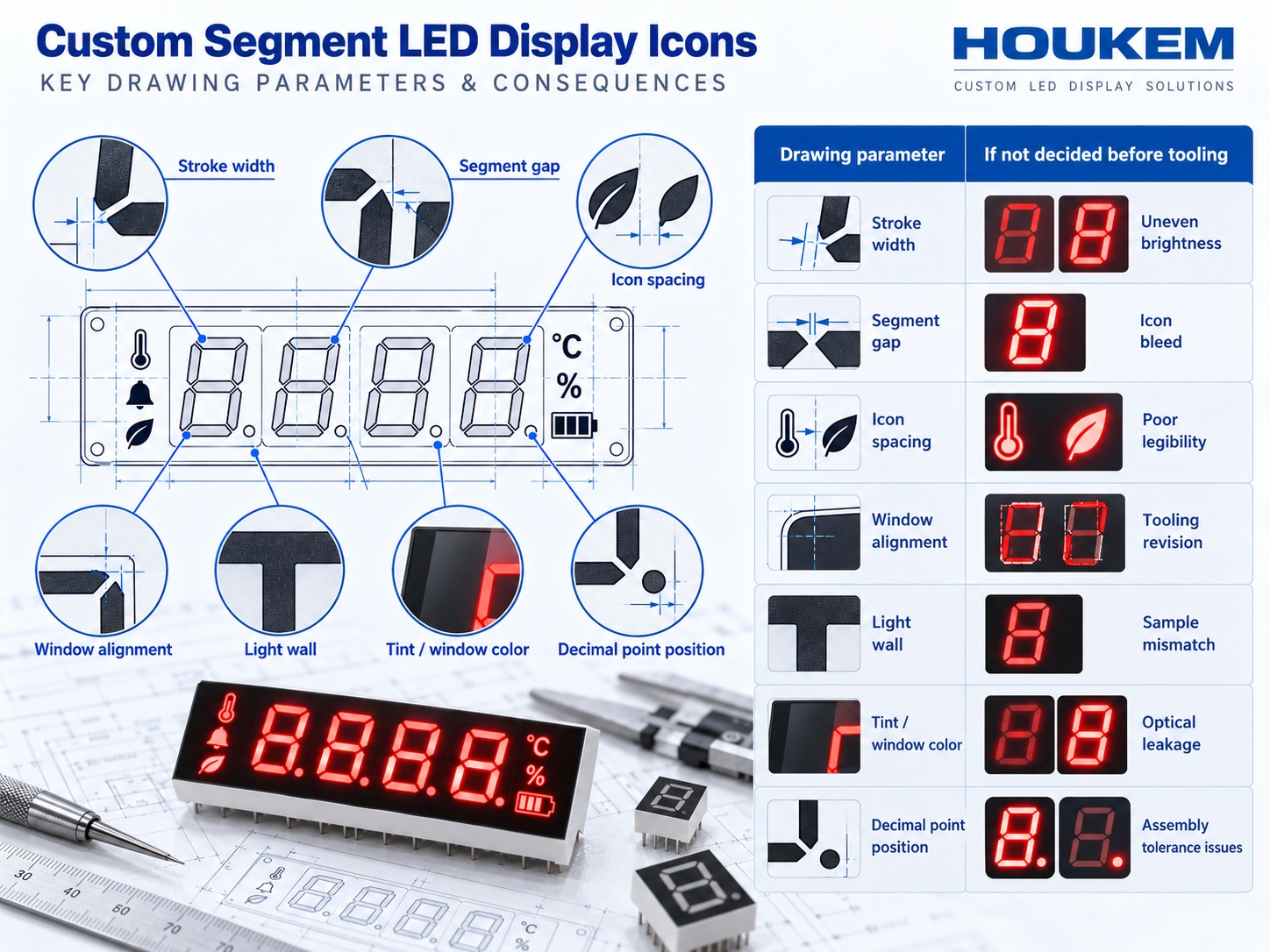
Stroke width is the first decision because it links the artwork to the viewing distance. An element that subtends too small an angle cannot be resolved, no matter how bright it is, and the threshold depends on the application rather than on the display alone.
Where an icon is made from several elements, the spacing between them is a second independent decision. Elements that are electrically separate but optically adjacent behave as a single shape when the gap is small, which changes what the user reads without changing anything the designer can measure electrically.
The third geometric decision is the relationship between the lit area and the legend printed around it. A custom panel often combines illuminated segments with printed symbols, and the two have to be aligned on the same drawing so that the lit element sits behind the intended opening rather than beside it.
Because these decisions travel together, they are normally captured on a single production drawing that also carries dimensions and tolerances. The fields that appear on that drawing, and how they are expressed, follow the conventions described in our guide to reading the display datasheet, which is the same information set seen from the buyer side.
Parameters to Fix Before Tooling Is Cut
The table below lists the parameters that should be frozen on the drawing, together with the consequence of leaving each one open. Every entry is a decision that a supplier will otherwise make on the buyer's behalf.
| Parameter | Why it must be fixed | What happens if it is left open |
|---|---|---|
| Stroke width and element length | Determines legibility at the viewing distance | The icon reads as a smudge and cannot be corrected electrically |
| Gap between adjacent elements | Prevents optical merging of separate indicators | Two status indicators appear as one continuous shape |
| Icon position relative to the window | Aligns the lit element with the printed legend | The lit area sits partly behind the bezel |
| Light control features | Keeps illuminated areas from leaking sideways | Unlit icons glow faintly and lose their meaning |
| Colour and wavelength per icon | Sets the contrast against the panel finish | Colour combinations arrive that the artwork did not allow for |
| Pin assignment and routing | Ties the electrical interface to the PCB footprint | The footprint has to be revised after the panel is approved |
Reading the table downwards gives a checklist rather than a specification. The useful step is to confirm that each row is present on the drawing being reviewed, because an omitted row is invisible at the review stage and expensive at the sample stage.
Icons, Annunciators and Legibility Limits
An icon carries meaning in less space than a digit, which makes it more sensitive to the geometry decisions above rather than less. A digit can be read from the arrangement of seven elements, while a symbol usually has to be recognised from its outline alone.
The practical consequence is that icons need a wider stroke relative to their size than digits do, because recognition depends on the closed shape staying closed. An outline that breaks at one corner stops reading as a symbol and starts reading as an artefact.
A second constraint comes from the panel itself. Tinted windows, anti-glare coatings and printed overlays all reduce the contrast between a lit and an unlit element, and they reduce it unevenly if the icon sits off the optical axis. Designing the icon on a white background and reviewing it under the final window is one of the most common sources of late changes.
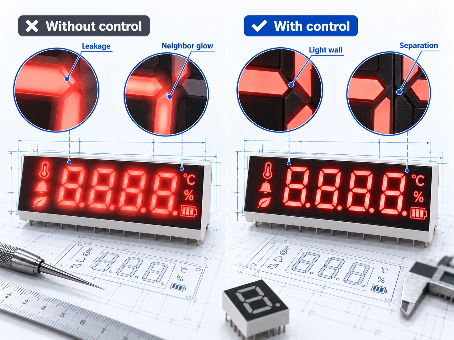
The third constraint is contrast rather than brightness. Increasing drive current raises both the lit and the leaked light, so it improves the appearance of the icon without improving its separation from its neighbours. Only the geometry and the light control features change that ratio, which is why they have to be settled in the drawing.
Validating the Design on a Sample
Validation means checking the physical sample against the drawing under the conditions the product will actually be used in, rather than on a bench under office lighting.
The three checks worth performing are the legibility check at the specified viewing distance, the separation check with one element lit and its neighbour unlit, and the alignment check with the intended window or overlay fitted. Each one tests a decision that was supposed to have been frozen, so a failure is a drawing problem rather than a sample problem.
Where the application needs a non-standard size or a symbol set that the standard range does not carry, the drawing review becomes the main risk-control step, and the customization path described in our overview of custom LED display solutions for OEM projects follows from it. Replacement of an existing module adds a further constraint, because the new drawing has to match the existing footprint and pin arrangement as well as the new artwork.
Once the sample passes, the approved drawing becomes the reference for production, and any later change to an icon shape, a colour or a pin assignment should re-enter the same review rather than be treated as a small edit.
Frequently Asked Questions
How to evaluate custom segment LED display icons for an OEM design?
Evaluate them against the viewing distance, the gap between adjacent elements and the light control shown on the drawing. Then confirm the same three points on a physical sample seen through the final window or overlay.
Which parameters matter most for custom segment LED display icons?
Stroke width relative to viewing distance matters most, because it decides whether the shape can be resolved at all. The separation gap and the light control features come next, because they decide whether adjacent icons stay visually distinct.
How does custom segment LED display icons affect LED performance?
The artwork changes how efficiently light reaches the user rather than how much the emitter produces. A narrow element with weak side walls loses a large share of its output, so the same emitter looks dimmer in a poorly designed icon than in a well designed one.
How should engineers validate custom segment LED display icons before production?
Check the sample at the specified viewing distance, then repeat with one element lit and its neighbour unlit to confirm the icons stay separate. Finish with the window or overlay fitted, because that is the condition the user will see.
Can an existing display be reworked with new icons?
Often yes, provided the footprint and pin arrangement stay compatible and the new artwork fits the existing window. The drawing review still applies, because the icon geometry is independent of whether the module is new or based on an existing assembly.
Conclusion: Sign the Drawing, Not the Sample
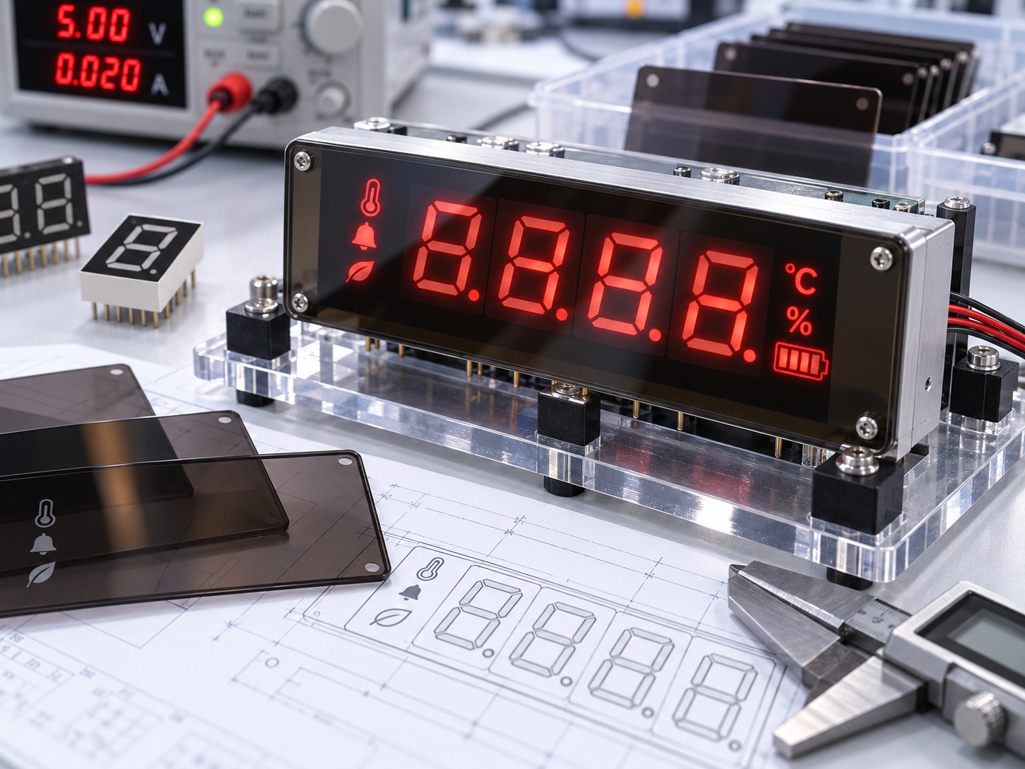
Custom segment LED display icons are decided by the drawing, and the sample only confirms that the drawing was followed. Freezing stroke width, separation and light control before tooling is what keeps the project from paying twice for the same decision.
The approach also makes Custom Display Integration work predictable, because custom LED display design and OEM display integration inputs are then recorded on one approved document instead of being distributed across a specification, an email thread and a supplier's assumption.
If you are preparing artwork for a panel and want the geometry and light control reviewed against the intended viewing condition, look at the custom LED displays range and the wider 7 segment LED displays platform, then send the drawing through the inquiry page.
How to Read an LED Reflow Soldering Profile