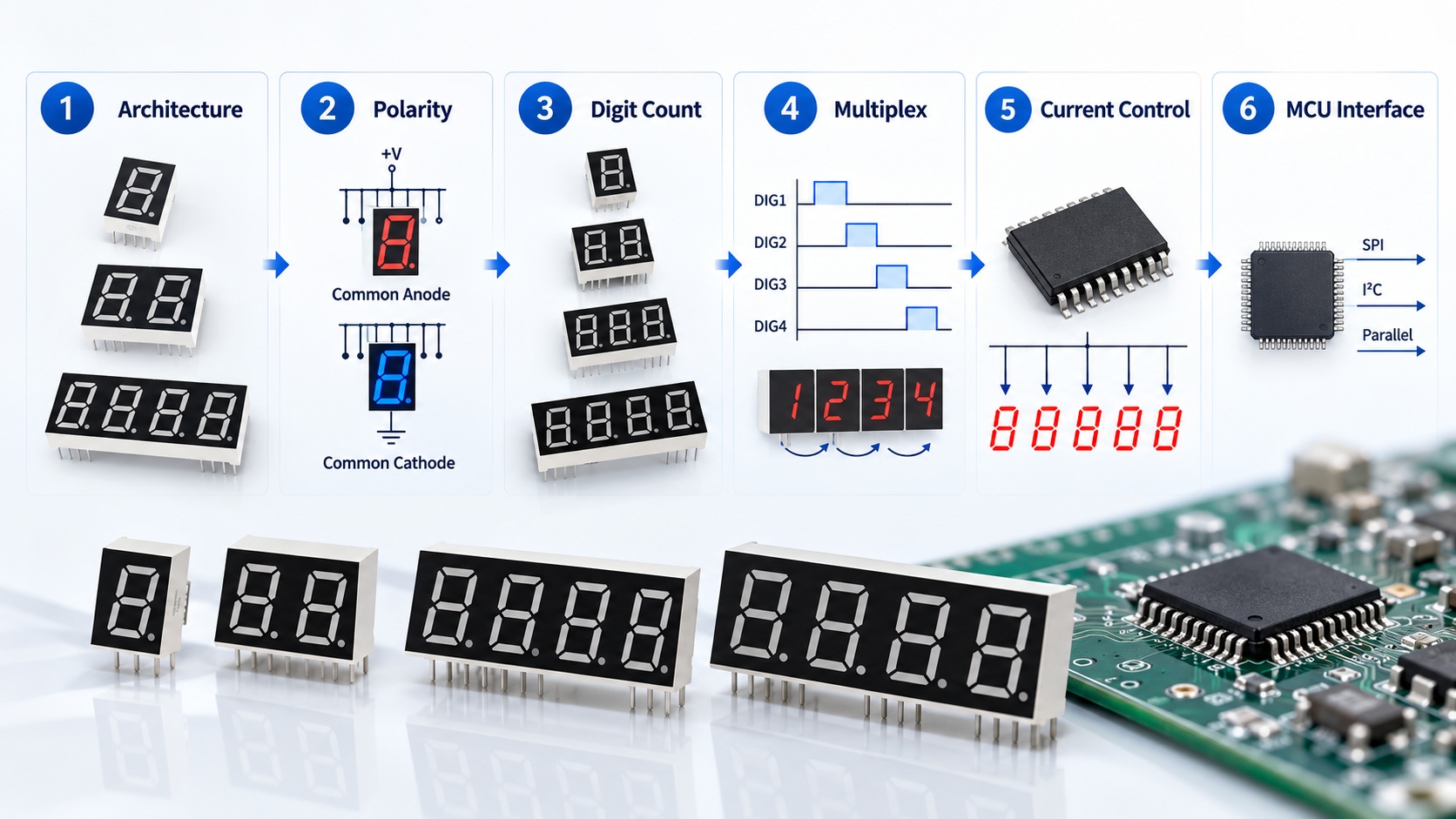
Large 7 Segment Display Driver Circuit: Driving Higher Segment Voltage

Quick Answer: What Changes in a Large Digit
The change is voltage, not current. A segment made of several emitters in series needs a higher forward voltage, so the supply must sit above that value with enough margin for tolerance and temperature, and the driver must still deliver the intended current.
That single change cascades. The logic supply may no longer be usable for the segments, the driver stage may need its own rail, and heat moves from the display to the driving components.

Parameters That Decide the Driver Design
Before any part is selected, sketch the large 7 segment display driver circuit and mark where the logic rail ends and the segment rail begins. That single sketch usually exposes the headroom problem before any component is chosen.
Five parameters set the constraints, and each one should be written down before a topology is chosen.
| Parameter | What it controls | Verification point |
|---|---|---|
| Segment forward voltage | Minimum supply headroom needed to reach rated current | Measured with the segment lit at operating temperature |
| Segment current | Brightness and long term stability of the digit | Measured per segment, not per digit average |
| Drive method | Whether digits are static or scanned and how duty cycle is set | Checked against the timing actually used by the firmware |
| Driver dissipation | Heat load in the driver stage and the required layout area | Case temperature measured in the finished enclosure |
| Supply tolerance | Behaviour at the lowest and highest admissible supply | Testing at both limits, not at nominal only |
Supply tolerance is the parameter most often skipped. A design that reaches its target current at nominal supply can fall short at the low limit and overdrive at the high limit.
Choosing a Drive Topology
Three arrangements cover most large digit designs. Direct drive from the logic rail only works when segment voltage stays low enough, which is rarely true for large formats. A separate segment rail with per-segment resistors is simple but makes current sensitive to supply and temperature. A constant current driver stage costs more parts but holds current steady as voltage drifts.
The choice also depends on whether the display is scanned. A scanned digit is on for only part of each cycle, so the current during the active window is higher than the average, and both the driver and the emitter must be able to take that peak for the duty cycle used. The relationship between scan ratio, duty cycle and peak current is explained in our article on multiplexing and scan ratio in LED displays.
When the topology question is still open, it is worth reading the selection criteria in our guide to 7 segment display driver IC selection, which covers interface, pin count and firmware fit alongside current control.
Current Setting and the Single Segment Case
Where each segment is driven independently, the current setting is the same calculation as for any LED string, but the numbers are larger. If the segment contains several emitters in series, the calculation must use the summed forward voltage of the string rather than the value for one emitter, and the resistor or driver must be sized for the resulting power. The step by step method is set out in our guide to current limiting resistor calculation for LEDs.
Where a segment is instead built from parallel branches, current sharing becomes the limiting factor, and small forward voltage differences between branches can produce visible brightness differences across a digit. The trade-offs involved are described in our article on LED series versus parallel wiring.

Layout and Thermal Considerations
Large digits concentrate current into a small number of driver channels. Trace width, copper area and the thermal path under the driver package decide whether the stage runs within its rating, and the display itself may need attention to how heat leaves the segments. In multi-digit LED display design the same driver stage is repeated for every digit, so a thermal or tolerance mistake is multiplied rather than averaged out.
Good 7 segment LED design keeps the driver stage and the display specification aligned from the first layout draft. The detail belongs to 7-Segment Drive & Circuit Design rather than to mechanical layout, because the decisions that matter are electrical ones. Large format capability should always be confirmed against the specific model and project, and the available options are summarised on our 7 segment LED display category page.
Validating the Driver Design on a Prototype
Prototype validation should test the conditions the product will actually meet. Measure segment voltage and current with the digit at operating temperature rather than at first switch-on. Confirm behaviour at both supply limits. Check the driver case temperature inside the finished enclosure, since a bench board on an open desk will read lower than the same circuit in a sealed housing.
Finally, check the scan timing in firmware against the timing the driver and emitter were specified for. A driver that passes on the bench can still fail in the field if the duty cycle assumed during design does not match the duty cycle the firmware produces.
Frequently Asked Questions
How to evaluate large 7 segment display driver circuit for an OEM design?
Write down segment forward voltage, segment current, scan method, driver dissipation and supply tolerance first. Then compare topologies against those constraints rather than against component price alone.
Which parameters matter most for large 7 segment display driver circuit?
Segment forward voltage and supply tolerance matter most, because they decide whether rated current can be reached at every admissible supply. Driver dissipation usually ranks next, since it affects layout area and enclosure design.
How does large 7 segment display driver circuit affect LED performance?
It sets the current each segment actually sees, which drives brightness and long term stability. Poorly controlled current can also create visible brightness differences between digits of the same display.
How should engineers validate large 7 segment display driver circuit before production?
Measure segment current and voltage at operating temperature and at both supply limits, then check driver case temperature in the finished enclosure. Confirm that firmware timing matches the duty cycle used during design.
Can a large digit be multiplexed like a small one?
Yes, but the peak current needed to reach the same average brightness is higher, so the driver and the emitters must both be rated for it. The practical limit is normally set by driver dissipation rather than by the display itself.

Conclusion: Driving Large Displays Without Guesswork
A large 7 segment display driver circuit is a voltage headroom problem before it is a components problem. Set the segment voltage and current from the real data, choose a topology that keeps current controlled across the supply range, and validate the design at operating temperature inside the final enclosure. That sequence removes most of the surprises that appear between prototype and production.
If you are designing a large format numeric display and want the digit specification, drive arrangement and availability confirmed before layout, send the requirements to our engineering team through the inquiry page.
7 Segment Display Driver IC Selection: How to Choose the Right Architecture