


How to Evaluate LED Display Brightness Uniformity

What Does LED Display Brightness Uniformity Actually Measure?
Uniformity describes how evenly brightness is distributed across the parts of a display that are meant to look identical. It is a relationship between measurements rather than a single measurement, which is why it must be defined before it can be specified.
| Scope | What is compared | Typical expression |
|---|---|---|
| Segment to segment within one digit | Each segment of the same character and colour | Ratio of the lowest to the highest segment reading |
| Digit to digit within one module | The same character position on every digit | Ratio of the lowest to the highest digit reading |
| Unit to unit within a lot | Identical module positions across sampled units | Spread between the dimmest and brightest sampled unit |
| Colour channel balance | Red, green and blue channels at the same position | Per-channel ratio, evaluated separately |
Note that the scope is part of the definition. A display can be highly uniform digit to digit and still show a visible difference between segment positions, and a lot can be uniform unit to unit while every unit shares the same internal imbalance.
Why Uneven Appearance Appears Even When Every LED Is In Spec
Uniformity problems rarely come from a defective part. They usually come from the spread that the specification already permits.
Binning spread across a lot
Emitters are graded into bins, and a lot built from different bins will show the difference between those bins once the parts sit side by side. Even a specification that allows a reasonable bin range can produce a visible mismatch if the extremes end up adjacent on one panel. The structure of those grades is explained in our article on how LED binning works.
Drive current and multiplexing behaviour
In a multiplexed display, not every position receives identical drive conditions, and small differences in duty cycle or driver channel tolerance become visible as brightness variation. Reducing overall power consumption usually means changing drive conditions, which is why power-saving revisions should always be re-checked for uniformity; our guide to reducing LED display power consumption covers the trade-offs involved.
Viewing angle and mechanical position
If two digits sit at different distances from the reader, or one is deeper in a bezel, apparent brightness differs even when measured values match on axis. Uniformity measured on a bench does not automatically predict how the assembled unit looks in a panel.
How to Measure Uniformity in Practice
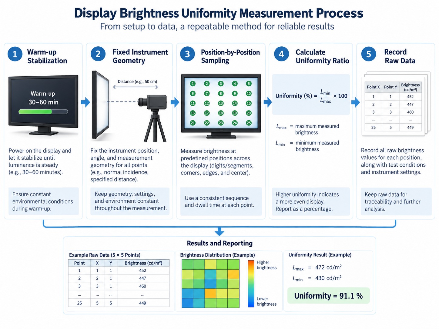
Reproducibility comes from fixing the measurement conditions, not from the instrument alone. Every LED display brightness measurement should be traceable to a stated geometry, warm-up state and drive condition, so that a second laboratory can repeat it and reach the same conclusion.
Fix warm-up, distance and angle
Let the sample reach stable thermal conditions before measuring, because output drifts as the junction warms up. Keep the instrument at a fixed distance and angle from each position, and measure every position from the same geometry so that differences reflect the display rather than the setup.
Sample every position, not just the brightest digit
Knowing how to measure brightness uniformity across digits means sampling every character position rather than only the strongest one. Measuring the brightest digit tells you almost nothing about uniformity, because uniformity is defined by the weakest position. Include the characters closest to the driver, the characters furthest from it, and, on a matrix, the corner pixels as well as the centre. The relevant brightness quantity itself is covered in our explainer on LED display brightness in mcd.
Record the raw data with the summary
Store the individual readings alongside the computed ratio. When a claim is later disputed, the raw data shows whether the difference came from one outlier position or from a gradual gradient across the panel, and those two cases need different corrective actions.
Setting an Acceptance Criterion for Your Project
| What to write into the requirement | Why it matters |
|---|---|
| The scope: segment, digit, module or lot level | A ratio is meaningless without the set of positions being compared |
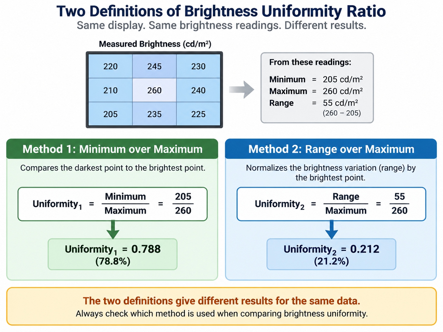
| The exact definition of the ratio | Minimum over maximum and maximum minus minimum over maximum give different numbers for the same display |
| The quantity being measured and its unit | Intensity, luminance and flux cannot be interchanged in a ratio |
| Drive current and duty conditions | Uniformity changes when the display is driven differently |
| Measurement geometry and instrument class | Angle and distance change the readings between laboratories |
| A sampling plan and acceptance point | Without a sample size, a criterion cannot be closed at incoming inspection |
A criterion built from these six items can be checked by a third party without further discussion. Any quoted brightness uniformity ratio should be traceable to the scope and definition it was calculated from, because the same display can produce two different ratios from two valid definitions. One missing element usually means the discussion restarts at delivery. For the readout families where uniformity matters most, the applicable parts sit within the 7 segment LED display range and the matrix formats.
Frequently Asked Questions
What uniformity ratio should I ask for?
There is no universal figure, because what is an acceptable brightness uniformity ratio depends on the viewing distance, the number of positions on the panel and how critical the appearance is. A large panel read from a distance tolerates more variation than two adjacent digits read close up, so the requirement should follow the application.
Is a tight bin enough to guarantee uniformity?
The brightness uniformity vs LED binning relationship is not automatic: a tight bin controls the emitter-level spread but does not control drive conditions, assembly geometry or bezel effects. Bin control is necessary for uniformity, but it is not sufficient on its own.
Should uniformity be measured at full brightness?
Most comparisons are made under the drive condition the product will actually use, because that is where the tolerances appear. If the display supports dimming, check at least one reduced level as well.
How many units should be sampled?
The sample must be large enough to include the extremes of the lot, which usually means taking units from different positions in the production run rather than several units from one tray. The sampling plan belongs in the written criterion.
Can uniformity change after the product is assembled?
Yes, because bezels, windows and light pipes redistribute light and can change the apparent relationship between positions. Verify the criterion on the assembled unit as well as on the bare module.

Conclusion
Brightness uniformity is a defined relationship, not a single reading, and it fails for ordinary reasons: permitted bin spread, drive asymmetry and assembly geometry. Measuring every position and writing the scope, definition, conditions and sampling plan into the requirement is what makes the criterion verifiable instead of negotiable.
If you are preparing an incoming or outgoing inspection requirement for a multi-digit or matrix display, send your display requirements to the HOUKEM team and we will confirm the applicable parts and the measurement conditions for your project.
How to Choose an LED Display for HVAC Controllers
How to Choose Red vs Green LED Display


