


7 Segment Display Driver IC Selection: How to Choose the Right Architecture
Define the Display Architecture Before Choosing Any IC
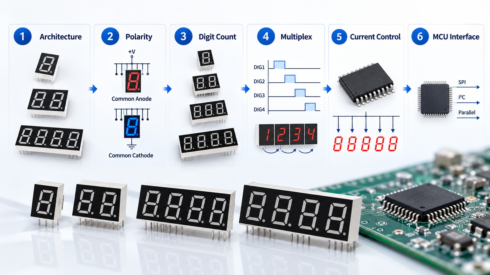
Three questions shape every driver decision. How many digits does the design need? Will each digit be driven continuously in static drive, or scanned one at a time in multiplexed drive? And is the display common anode or common cathode? Digit count and drive method determine how many segment and digit lines the driver must control; a four-digit multiplexed design needs far fewer lines than a four-digit static one, at the cost of scan timing and peak-current planning. HOUKEM supplies 7 segment LED displays in 1 to 6 digit configurations with common anode or common cathode options on model pages, so the driver discussion usually starts once the display format is fixed; the 7 segment display product range shows the formats involved.

Polarity: Driver IC for Common Anode vs Common Cathode Display
Polarity decides where the driver sources and sinks current. A common anode display ties all anodes to the digit line, so the driver switches the high side of each digit and sinks current from the segment cathodes. A common cathode display does the opposite. Choosing a driver IC for common anode vs common cathode display wiring is therefore not a preference; it is a hard compatibility check between the IC's output structure and the display. Some classic driver families only fit one polarity comfortably, and level-shifting or inverting stages can bridge the gap but add parts and failure points. Our comparison of common anode vs common cathode 7 segment displays walks through the electrical detail.
Current Control: Resistor per Segment or Constant Current
With static drive at modest current, a series resistor per segment is often the whole story. As digit count and multiplexing grow, peak segment current grows with them, and simple resistive control starts to produce visible brightness variation between digits. That is where a constant current driver for 7 segment display designs earns its place: it regulates segment current directly, keeps brightness uniform across the scan, and reduces sensitivity to supply-voltage variation. The trade-off is a higher-parts-count board and a driver whose current setting must match the display's rating, so verify the register or pin-strap current setting against the display datasheet rather than assuming it.
Multiplexing and the Scan Budget
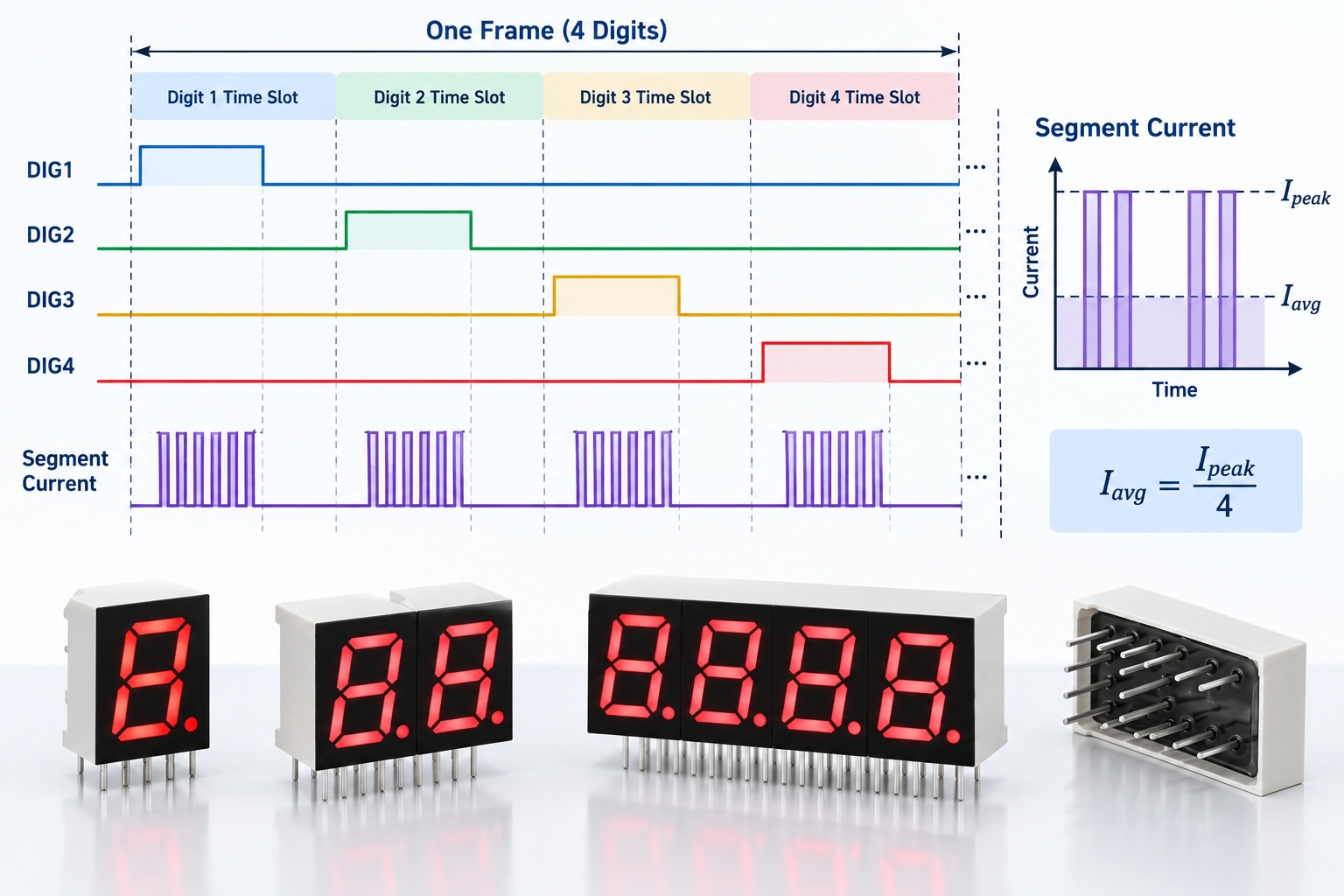
Multiplexed drive shares one set of segment lines across digits and lights each digit for a fraction of the frame time. The driver must sustain higher peak current during each digit's slot, and the firmware or driver IC must refresh fast enough to avoid flicker. When a multiplexed 7 segment display driver selection is made without checking the scan budget, the usual symptoms are dim outer digits, uneven brightness between sparse and dense segment patterns, or camera-visible flicker. Our article on LED multiplexing in display designs explains the timing arithmetic; apply it to the digit count you actually ship.
Interface, Pin Count and Firmware Fit
The last compatibility layer is the connection to your controller. Direct GPIO drive needs one line per controlled segment or digit and suits small static designs. Serial-interface driver ICs, whether shift-register inputs or bus devices with onboard memory and brightness control, trade a few control lines for pin savings and firmware simplicity on higher digit counts. Choose based on the controller's spare capacity, the board's routing space and how much brightness-control granularity the product needs. For LED display driver selection in cost-sensitive products, direct drive plus resistors is still a legitimate answer; the checklist below is how to confirm that deliberately instead of by accident.
7 Segment Driver IC Selection Criteria: The Checklist
| Check | What to Verify | Why It Matters |
|---|---|---|
| Display polarity | IC output structure vs common anode or common cathode | Hard electrical compatibility |
| Digit count and drive method | Segment and digit line count vs static or multiplexed plan | Defines the whole driver architecture |
| Current control | Resistor or regulated current; setting vs display rating | Brightness uniformity and derating safety |
| Peak and average current | Multiplex duty cycle vs IC and display limits | Prevents dim digits and overstressed segments |
| Interface and voltage | Logic levels, control lines, 3.3V or 5V compatibility | Guarantees clean timing with the MCU |
| Availability and second source | Lifecycle status and substitute options | Protects long-lifecycle OEM products |
If you are wondering how to choose a driver IC for a 7 segment display in one sentence: fix the display architecture first, then reject any IC whose polarity, current capability and scan behaviour do not match it, because the remaining candidates are chosen on interface and availability, not on feature lists.
Frequently Asked Questions
Do all 7 segment displays work with the same driver IC?
No, polarity, digit count and current rating must all match the IC's output structure and current setting. The display datasheet and the driver datasheet need to be checked together.
Why do my multiplexed digits have uneven brightness?
Uneven brightness usually comes from peak-current limits, scan timing or resistive control interacting with multiplexing. Check the duty cycle budget and consider a constant-current driver for uniform segment current.
Is a constant-current driver always the better choice?
It is the better choice when digit count, multiplexing or supply variation makes resistive control unstable. For small static designs at modest current, series resistors remain simple and adequate.
What defines the main 7 segment driver IC selection criteria?
Polarity compatibility, digit and line count, current control quality, scan behaviour, MCU interface and component availability. Electrical fit comes first, and features and price only rank the survivors.
Can one driver IC handle both common anode and common cathode displays?
Only if its output structure supports sourcing and sinking in the required places, which is uncommon in classic families. Treat polarity as a fixed input to the selection, not a switchable option.
Bringing the Driver Decision Together
Driver problems are almost always architecture problems discovered late. Fixing the display architecture, polarity, current-control method and scan budget first turns 7 segment display driver IC selection from a datasheet scavenger hunt into a short, checkable process. If you are scoping a new display project and want the display and driver constraints confirmed together, contact HOUKEM with your requirement and the engineering team can review the format, digit count and drive method with you.
How to Choose an LED Display for HVAC Controllers


