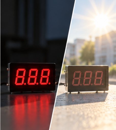
7 Segment Display PWM Dimming: Brightness Control Without Color Shift

Quick Answer: Dim by Time, Not by Current
Pulse-width modulation keeps the segment current constant and varies the fraction of each period during which the current flows. Average light output follows the on-time, and the instantaneous drive condition, which is what sets wavelength and forward voltage, does not change.
Three numbers describe the dimming path: the resolution, which is how finely the on-time can be divided; the frequency, which is how often the cycle repeats; and the duty budget that the scan already consumes. Get those three right and the display dims evenly. Ignore them and the panel either flickers, bands on camera, or dims unevenly between digits.
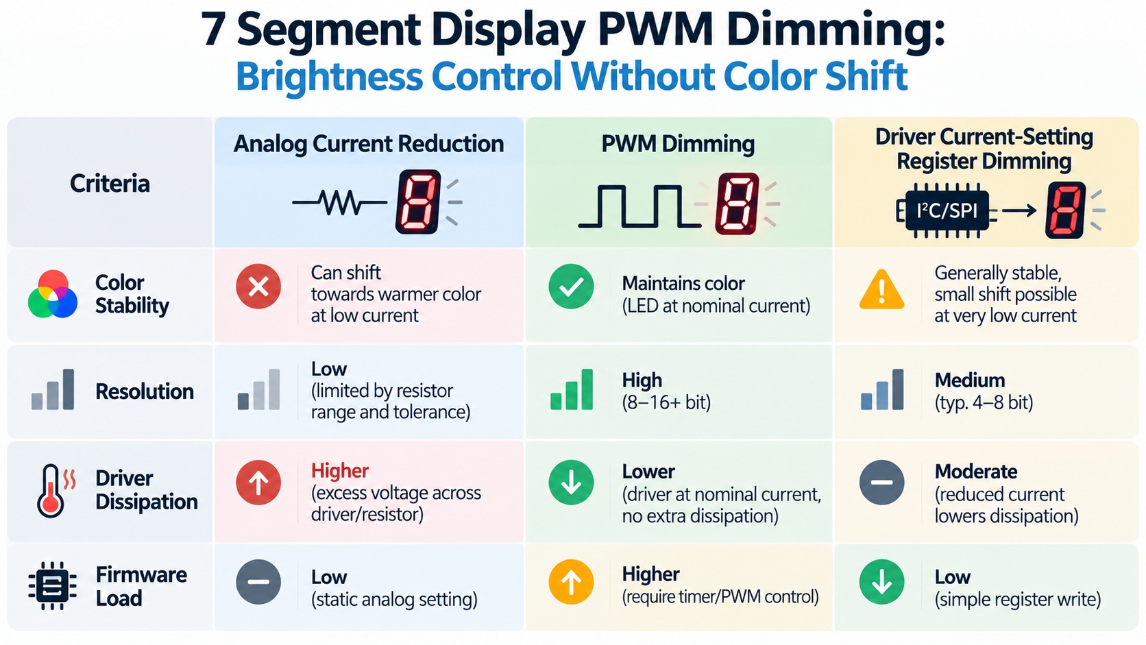
Why Current Dimming Changes the Colour
A forward-biased LED converts current into light, but not at a fixed conversion ratio and not with a fixed spectrum. As drive current falls, the emission peak moves slightly and the ratio between the wavelength regions shifts, so a display dimmed by current alone can move toward red or violet depending on the die and the phosphor system.
The effect is small at each step and visible when several digits sit at different dimming levels. A numeric display rarely dims uniformly across the panel to begin with, because multiplexing means each digit is only lit for part of the frame, and any additional variation between digits becomes a brightness gradient that users notice before they notice the absolute level.
The same reasoning is why a display that is passing on the bench can behave differently once the firmware runs. A sample driven at a fixed current looks perfectly even, while a duty-cycle-controlled product shows the differences between its digits. That is the check our guide to scan ratio and duty cycle in a multiplexed display describes from the scanning side.
Three Ways to Dim a Numeric Display
Dimming can be implemented in more than one place, and the choice interacts with the driver already on the board.
| Method | What it changes | Trade-off to expect |
|---|---|---|
| Analog current reduction | Steady current through every segment | Simple and free of switching artefacts, but the dimmed colour differs from the full-brightness colour |
| PWM at the driver output | On-time of the segment current | Colour holds across the range, but resolution and frequency must be chosen together and driver switching losses rise |
| Driver-register brightness setting | Internal pulse width inside a display driver | Removes firmware work and keeps colour stable, at the cost of a fixed set of levels and a dependency on the driver |
Where a driver is already in the design, the register route is usually the cheapest because it reuses the switching stage that is already there. Where segments are driven from discrete transistors, the pulse has to come from the controller, and the choice between the two remaining rows becomes a question of how much firmware load the project can carry. Driver capabilities in this area are covered in our guide to driver IC selection and current setting.
Frequency, Resolution and the Limits They Impose
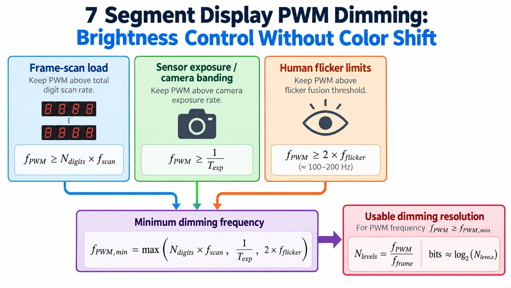
Dimming frequency and dimming resolution are not independent, and neither can be chosen without reference to the scan. In a multiplexed display the digit is already being switched at the frame rate, so the dimming pulse has to be nested inside the digit's own on-time rather than applied to the whole frame.
Resolution is therefore a division of a window that has already been shortened by scanning. A common error is to specify a fine dimming step, for example one step in a few hundred, without checking whether the digit's on-time is long enough to contain it. When the window is too short, the low end of the dimming range collapses, and the display drops from visible to off instead of fading.
Frequency is bounded from below by flicker. The eye integrates pulsed light above a few tens of hertz, but a display that is scanned and dimmed at the same time presents a lower effective repetition rate than either number suggests, and camera-based products raise the limit further because a sensor with a short exposure will catch individual pulses. How a panel behaves under those conditions is the practical reason to test a dimmed sample on camera rather than by eye alone.
The power consequence runs the other way. Dimming reduces average current, and where a display spends most of its life dimmed, the driver dissipation and the supply sizing should be recalculated for that condition rather than for full brightness. The available options are summarised in our overview of hardware methods that reduce display power.
What Dimming Does to Segment Current and Voltage
Keeping the current constant during the on-time does not make the electrical design disappear. Each segment still needs its current-limiting element sized for the full on-current, and a large-digit design that switches several segments together still has to supply the summed current during the pulse, which is the sizing question covered in our guide to segment voltage in a large-digit driver.
There is a second, less obvious constraint. A dimmed display runs its segments briefly at full current, so the junction experiences a short peak rather than a sustained level, and the average temperature falls even though the instantaneous drive is unchanged. The sizing method for the limiting element is the same one used at full brightness, and it is set out in our guide to which segment to drive with a shifted current.
Where the display shares a supply rail with other circuitry, the pulsed load also becomes a supply question. The pulse current has to be available on demand, and a regulator sized only for the average will sag during the on-time, producing a brightness change that looks like a dimming fault but is really a supply fault.
Validating a Dimmed Display Before Production
Validation has to exercise the firmware, because the dimming path lives there. A bench sample driven at a fixed duty cycle proves the display and not the product.
- Drive the real firmware at the minimum and maximum dimming levels and confirm the display fades rather than switching off at the low end.
- Compare every digit at the same dimming level, since unequal on-times between digits show up as a gradient before they show up as a fault.
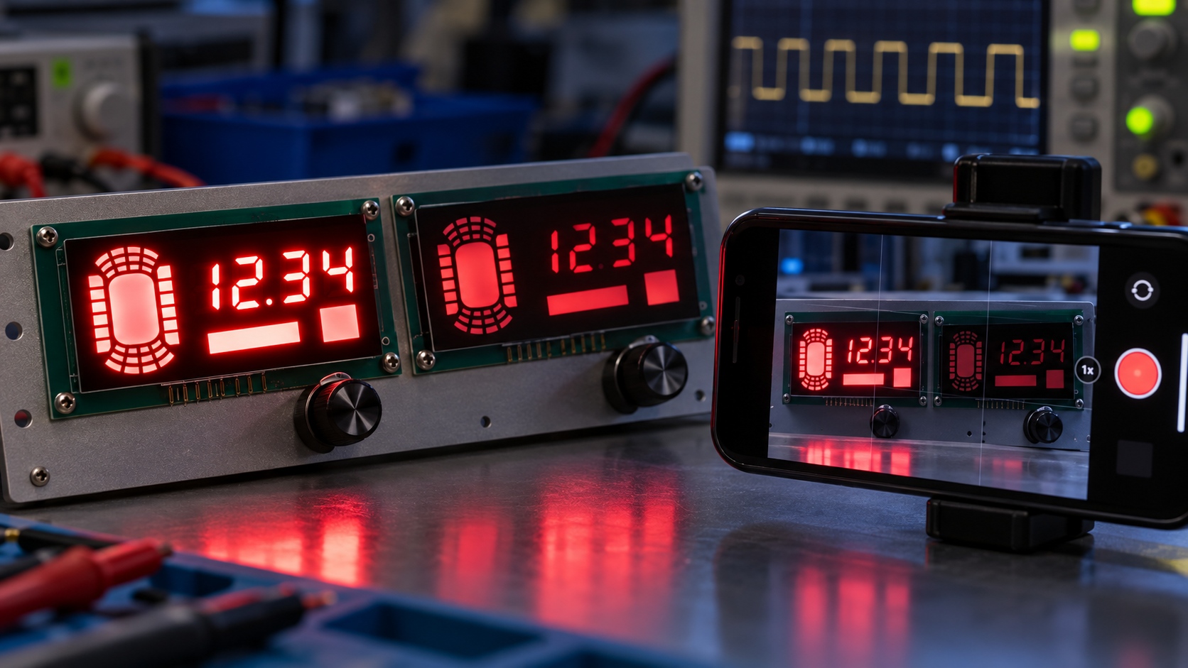
- Record the panel on a camera at the exposure the product will actually use, and check for banding or roll artefacts.
- Measure the supply rail during the on-time at the highest dimming level, so the pulsed load is verified rather than assumed.
- Repeat the whole set at the temperature extremes of the enclosure, because driver switching behaviour and display output both move with temperature.
Step four catches the failure mode that survives every optical check, because the display looks correct until the supply is loaded in the finished product. Recording the result at that point turns an intermittent complaint into a specified condition.
Frequently Asked Questions
How to evaluate 7 segment display PWM dimming for an OEM design?
Start from the dimming range the product needs and the frequency the application tolerates, then check whether the scanned digit window is long enough to hold the requested resolution. Confirm the result with the real firmware rather than a bench duty cycle.
Which parameters matter most for 7 segment display PWM dimming?
Dimming resolution and dimming frequency matter most, because together they set how smoothly and how flicker-free the display dims. The duty budget left after scanning is what limits both of them.
How does 7 segment display PWM dimming affect LED performance?
It holds the instantaneous drive condition steady, so wavelength and colour stay close to the full-brightness value across the dimming range. It also reduces average current and average junction temperature while leaving the segment peak current unchanged.
How should engineers validate 7 segment display PWM dimming before production?
Run the production firmware across the full dimming range and compare every digit at the same level, then record the panel on the camera the product uses. Measure the supply rail during the on-time and repeat at the enclosure temperature extremes.
Does dimming reduce the load on the driver?
It reduces average dissipation but not the switching duty, because the driver still switches the full segment current during every pulse. A driver chosen only on average current can therefore run hotter than expected.
Conclusion: Specify the Dimming Window
7 segment display PWM dimming is easiest to specify as a window rather than as a level: a resolution, a frequency range and the scan duty that remains available for both. Once the window is written down, the driver and firmware choices follow from it, and the display dims without changing colour.
The approach also makes 7 segment LED design, multi-digit LED display design and 7-Segment Drive & Circuit Design decisions reviewable, because each dimming choice is recorded with the timing that supports it. That is what allows a second build to reproduce the same dimming behaviour instead of re-tuning it on the bench.
If you are specifying a dimmed numeric display and want the drive, resolution and switching limits confirmed for the actual application, send the panel size, digit count and intended dimming range through the inquiry page.
BJT vs MOSFET 7 Segment Display Driver Choice for Multiplexed Designs
Custom Segment LED Display Icons: What to Define Before Tooling