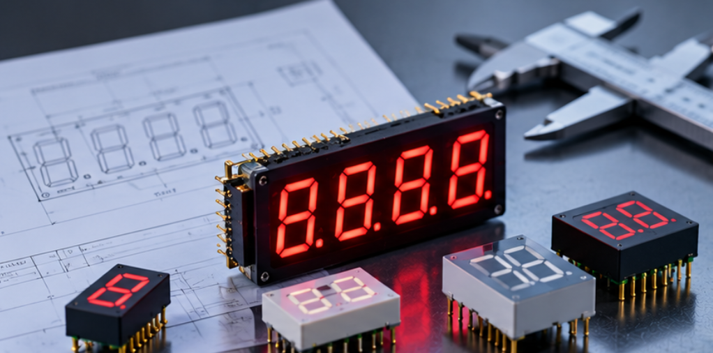
Shift Register 7 Segment Display Design: When One IC Simplifies MCU I/O
This guide covers the parameters that decide whether the approach is worth using, how the current budget and latch timing constrain the circuit, and what to check on the bench before the design is released.
Quick Answer: What a Shift Register Changes
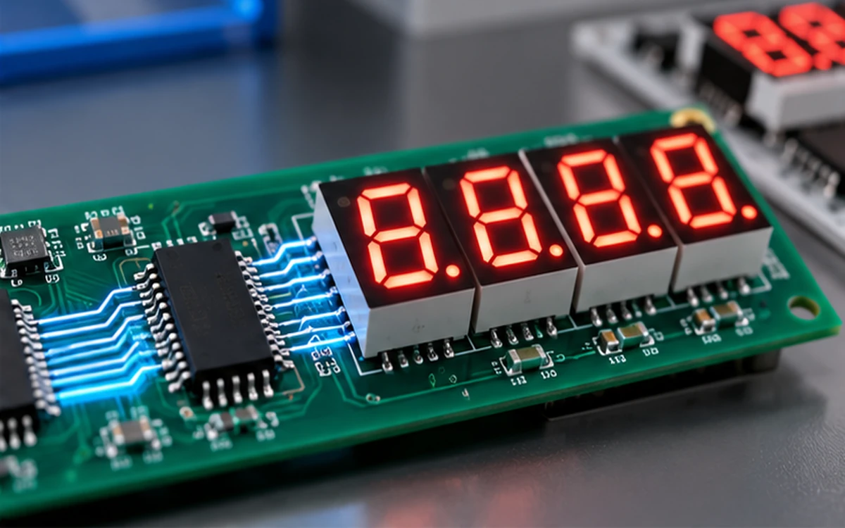
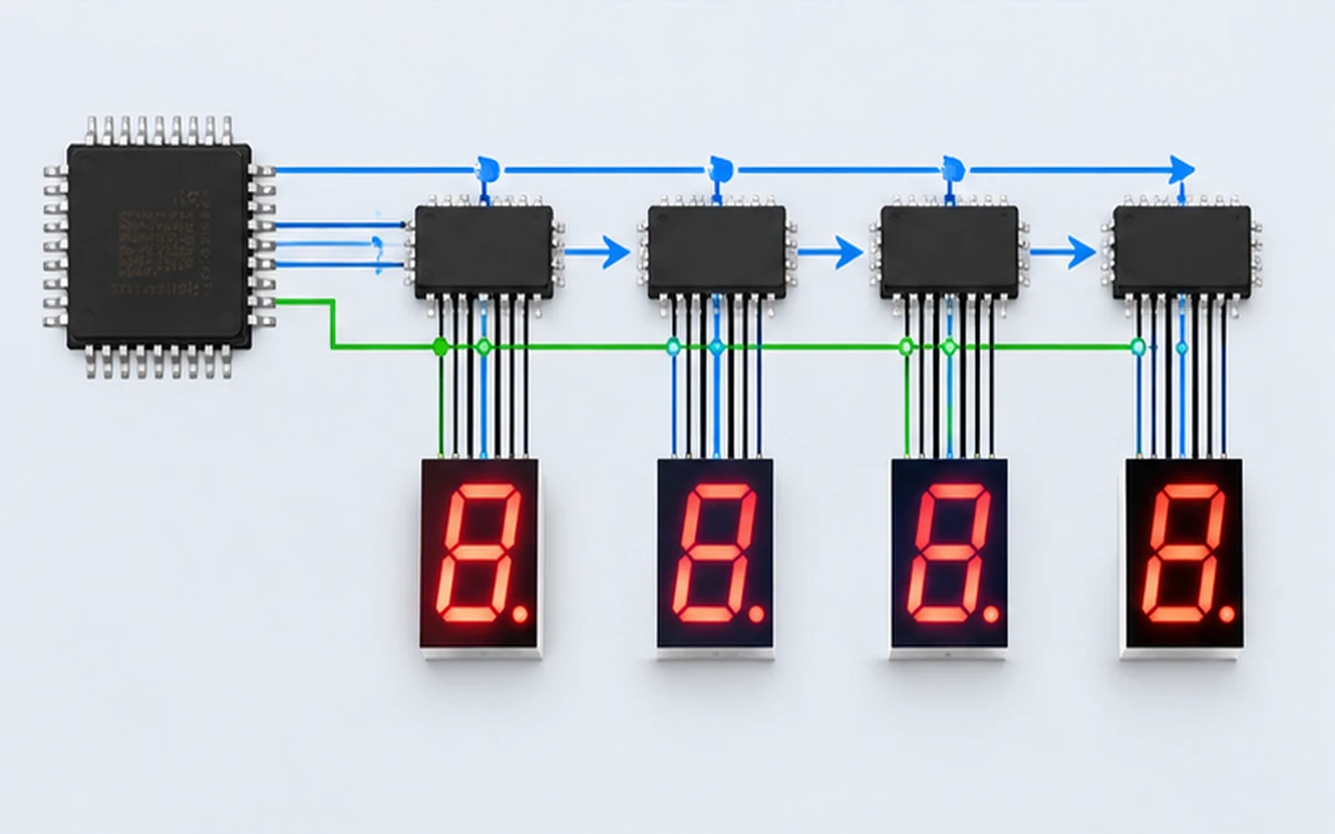
A shift register converts a serial bit stream into parallel outputs. The microcontroller sends bits in order, and the register holds each bit on its own output pin until the next transfer.
That means segment control for eight segments arrives over two or three microcontroller pins instead of eight, and cascading a second device extends the same bus to more digits without adding pins.
The cost is timing. The firmware must clock every bit out on every refresh cycle, which consumes processor time and creates a refresh rate ceiling that depends on the clock speed the design chooses.
Governing Parameters: Current, Timing and Latch Behaviour
The first parameter is output current per channel. A shift register output sources or sinks a defined current, and that number sets the maximum segment current and therefore the achievable brightness for the drive scheme in use.
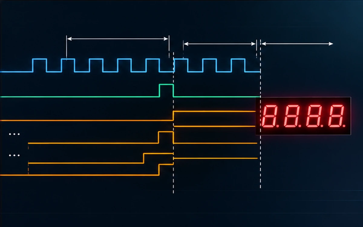
The second is the latch. Most practical devices separate the shift register from an output latch, so new data can be clocked in while the previous pattern stays visible. Designs that omit the latch update the panel one segment at a time, which produces visible tearing on a multiplexed panel.
The third parameter is refresh budget. For a 7 segment LED design the usable refresh rate is the serial transfer time for all digits plus the segment settling time, and the two together have to fit inside the flicker limit the application can tolerate.
| Parameter | What it changes | How it is set |
|---|---|---|
| Output current per channel | Maximum segment brightness | Register rating and series resistor |
| Shift clock frequency | Fastest achievable refresh | Bus speed and firmware loop time |
| Latch arrangement | Whether updates are seamless | Device selection and update routine |
| Number of cascaded devices | Digits and LEDs supported | Panel size and pin count |
Selecting a device that matches the current and timing envelope is normally a firmware and hardware decision taken together. The comparison criteria we set out in our guide to 7 segment display driver IC selection apply directly, because a serial register and a dedicated display driver solve overlapping problems.
How to Size the Approach
Start from the pin budget. Count the pins the product needs for sensing, communication and control, then see what is left for the display. If the remainder is fewer than the segment and digit count demands, a serial bus is already justified.
Then check the current budget. Multiply the required segment current by the number of segments lit at once under the chosen multiplex scheme, and confirm the register and its package can carry that load continuously. The arithmetic is the same one used for 7 segment display current consumption, with the register outputs added as a load path.
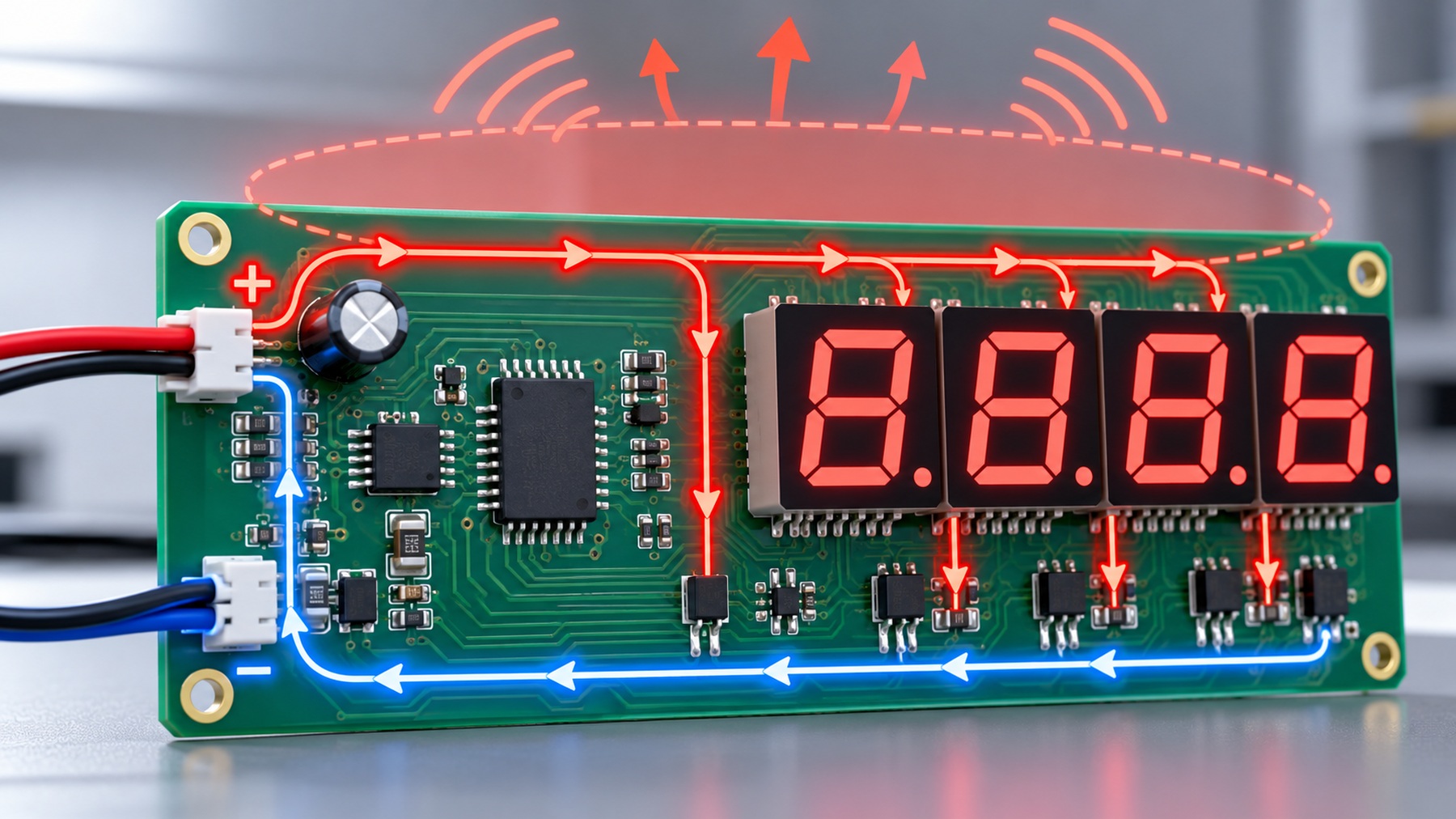
Finally, check the wiring topology, because the register sits between the supply and the segments and inherits the polarity of the panel. Common anode and common cathode arrangements place the switching device on opposite sides, and the choice changes how the outputs are configured. Our note on common anode versus common cathode wiring explains how that decision propagates through the circuit.
For a multi-digit LED display design that grows past two or three digits, the alternative is often a dedicated driver rather than a longer register chain. Our article on the large 7 segment display driver circuit shows the point at which the added logic stops paying for itself.
Trade-offs That Decide the Approach
The main trade-off is processor time against pins. A serial approach spends firmware cycles on every refresh and returns pins for other functions. Whether that exchange is attractive depends on how tight the processor budget is and how much headroom the loop has.
The second trade-off is board area. Cascaded registers add a package per eight outputs, which can cost more area than a single integrated driver even though each individual device is cheap.
The third is failure behaviour. A register chain fails as a chain, so one device or one joint can blank several digits at once. The specification should state whether that is acceptable and what the firmware does when a transfer is not acknowledged.
None of these trade-offs is decided by device price. They are decided by the pin count, the refresh requirement and the mechanical constraints of the panel, which is why 7-Segment Drive & Circuit Design is settled before the bill of materials is frozen.
Verification and Specification Checklist
On the bench, confirm the measured segment current at each output rather than trusting the nominal rating, because package temperature and simultaneous-channel effects both reduce the usable figure.
Then verify the update sequence. Drive a worst-case pattern, such as all segments on one digit and a single segment on the next, and watch for ghosting or tearing at the latch edge. This is where the effect of missing a latch shows up first.
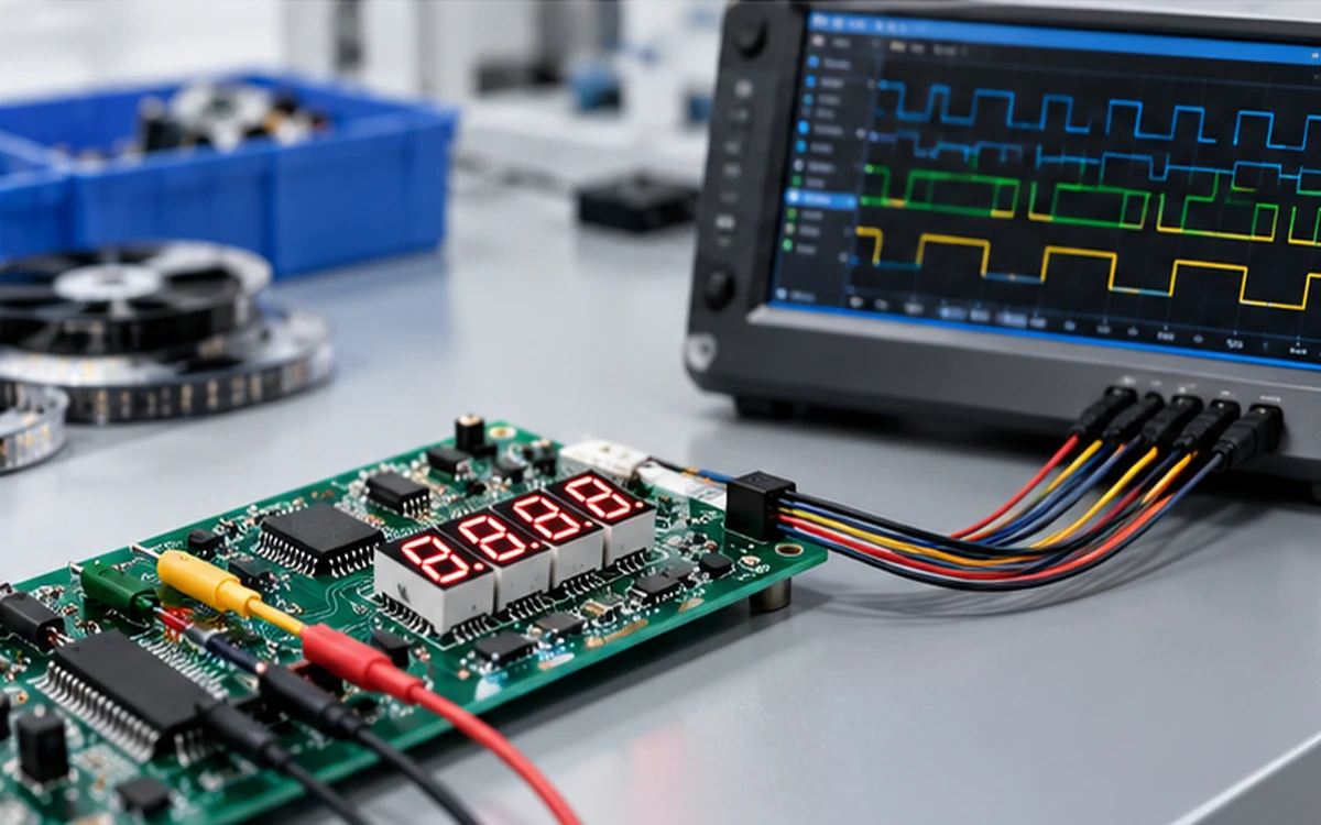
Measure the refresh interval with an oscilloscope and confirm it sits inside the limit set for the application. A refresh that looks acceptable in a laboratory is often unacceptable on a camera, and the resolution of that question belongs to the specification, not to the first customer complaint.
Record the accepted configuration, because the transfer order, the wiring polarity and the current setting are a matched set. Changing any one of them after release invalidates the others, and the record is what makes the change reviewable.
Frequently Asked Questions
How to evaluate shift register 7 segment display for an OEM design?
Compare the microcontroller pins the display needs against the pins available, then confirm the register can carry the required segment current under the chosen multiplex scheme. If both checks pass, evaluate the firmware time that the serial transfer consumes on every refresh cycle.
Which parameters matter most for shift register 7 segment display?
Output current per channel, shift clock frequency and latch behaviour matter most, because together they set brightness, refresh rate and update smoothness. The number of cascaded devices follows from the digit count and the pin budget.
How does shift register 7 segment display affect LED performance?
It affects achievable brightness and refresh rather than the emitter itself, because the register sets the current each segment can receive and the rate at which the pattern updates. A register that cannot carry the multiplex current will show dim or uneven digits even with correct firmware.
How should engineers validate shift register 7 segment display before production?
Validate by measuring segment current at each output, then driving a worst-case pattern and watching for tearing or ghosting at the latch edge. Measure the refresh interval with an oscilloscope and confirm it stays inside the application limit.
Can a shift register replace a dedicated display driver?
It can for small panels where the total segment current and refresh demand stay inside the register ratings. Once the digit count or the current requirement grows, a dedicated driver usually wins on board area and firmware simplicity.
Conclusion: Trade Pins for Timing Deliberately
A shift register 7 segment display design is a deliberate exchange of microcontroller pins for serial timing. It works when the pin budget is tight, the current fits the register rating, and the firmware can meet the refresh interval the application needs.
The decision should be made from measurement, not from a preference for fewer components. Build the pin and current arithmetic first, confirm latch behaviour on a prototype, then freeze the circuit. If you want the segment current and wiring options confirmed for a specific panel, send your digit count and supply details to the HOUKEM team and we will confirm the applicable display scope.
Multiplexed LED Display EMI: Scan Edges, Wiring and Driver Layout
7 Segment Decimal Point Colon Wiring: Planning Extra Segments in a Multi-Digit Display