LED Display for EV Charger: Specifying Readability, Sealing and Interface Fit
This guide converts those conditions into specifications a supplier can quote against, and sets out what to validate on the final product before the display design is frozen.
Quick Answer: What the Charger Front Panel Has to Do
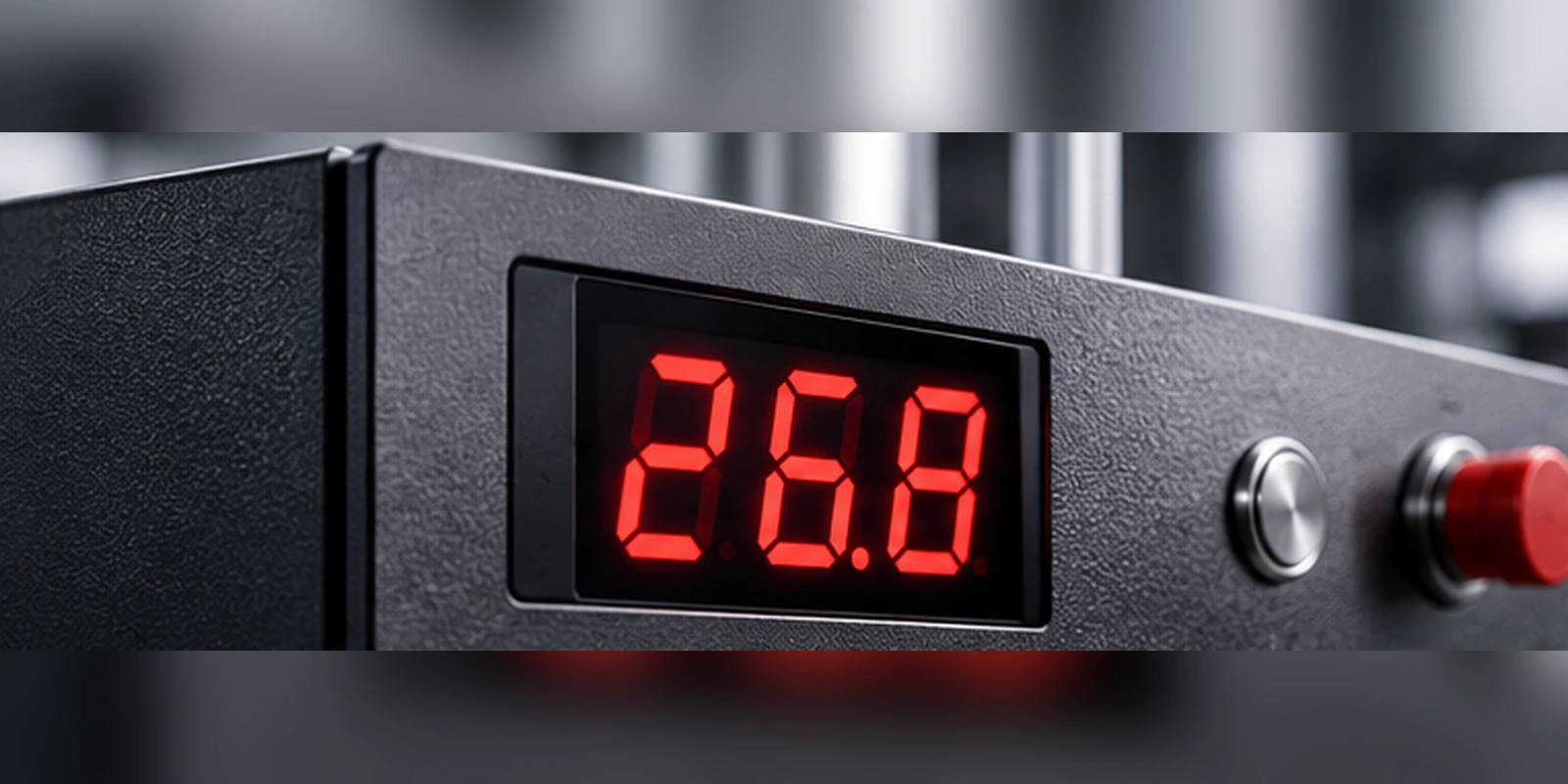
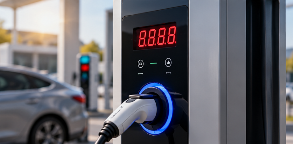
The display has to be legible in direct sun at the working distance, dim enough at night not to glare, and stable across the temperature range inside the enclosure. Missing any one of those produces a charger that looks correct on a bench and fails in the field.
It also has to survive the enclosure rather than exist beside it. Window material, gasket compression, cable entry and the internal air path all affect the display, and each of them is usually owned by a different part of the mechanical design.
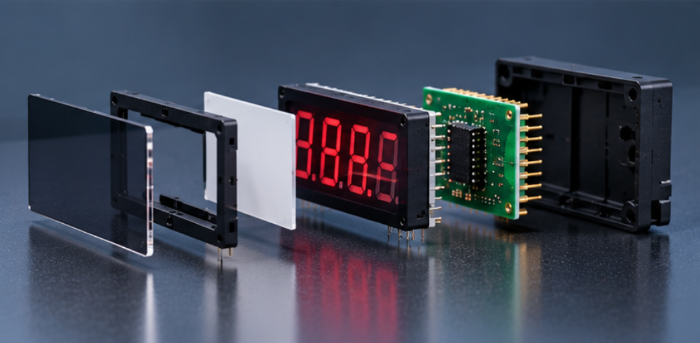
Treat the display as an assembly rather than a component. OEM LED display selection for a charging post is mostly a question of which assembly survives the site, not which module has the best datasheet numbers.

Reading Conditions: Sunlight, Glare and Night Dimming
Direct sunlight on a front window can exceed the display's own luminance by more than an order of magnitude, which is why contrast rather than raw brightness decides readability. A display with a dark background and a narrow emission window holds contrast far better than a bright diffuse one.
The sun angle matters as much as the sun intensity. A kerbside post facing east is lit at low angle in the morning, when the beam is close to the driver's line of sight, while a wall-mounted unit under a canopy may never see direct sun on the window at all.
Night dimming is the other half of the same requirement. A display specified only for daytime readability will be painfully bright after dark, so the dimming range, the control method and the minimum usable level all belong in the specification. Our article on sunlight readable 7 segment display covers the contrast and window options in more detail.
| Installation | Main readability problem | Specification to fix early |
|---|---|---|
| Kerbside post, open sky | Low-angle sun across the window | Peak brightness plus contrast treatment and a wide dimming range |
| Car park wall, canopy | Mixed shade and reflected light | Uniform brightness across the digits and a defined viewing cone |
| Indoor garage | Low ambient light, glare at night | Minimum dimming level and flicker-free drive |
| Retrofit into an existing housing | Fixed window size and depth | Digit height against viewing distance, plus module depth |
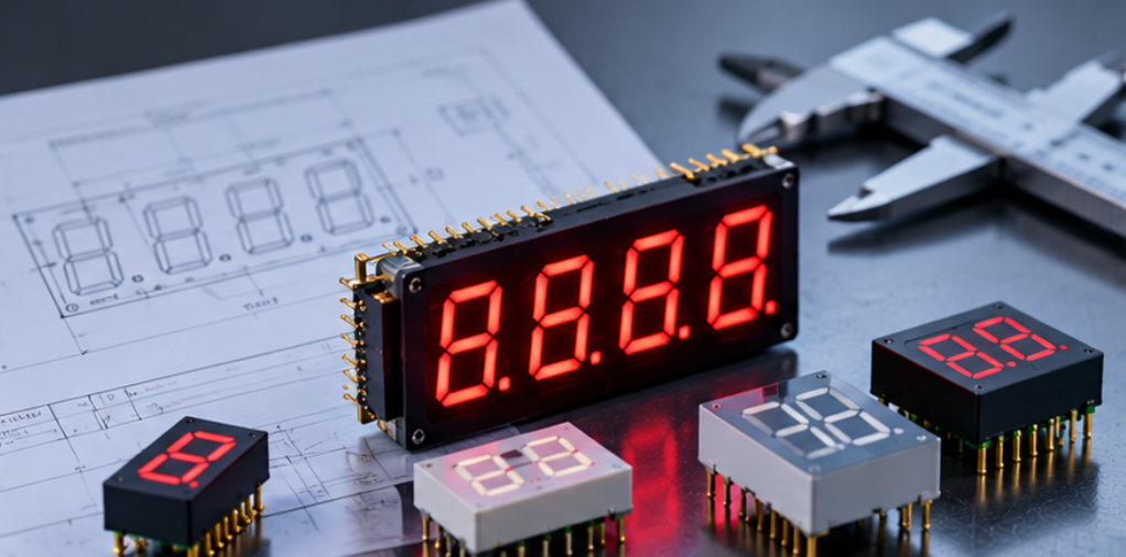
Digit height follows from the viewing distance rather than from preference. The LED display size and digit height guide sets out the ratio engineers usually apply, and it is worth fixing that number before the housing is drawn.
Sealing, Condensation and Thermal Cycling
A sealed enclosure does not remove moisture; it traps whatever entered during assembly. The display window is usually the largest flat surface on the front panel, so it is also the coldest surface at night and the first place condensation appears.
Gasket compression, window thickness and the stiffness of the front panel decide whether the seal stays uniform over temperature. A gasket that is compressed at the corners and relaxed in the middle will pass an initial leak test and fail after a few hundred thermal cycles.
Thermal expansion needs to be designed rather than absorbed. The window, the segment module and the PCB expand at different rates, and a rigid bond between them turns normal cycling into stress on the solder joints or the window edge. Our note on custom LED display drawing approval covers the dimensions and tolerances that should be fixed on the drawing so the seal and the optical alignment are both defined.
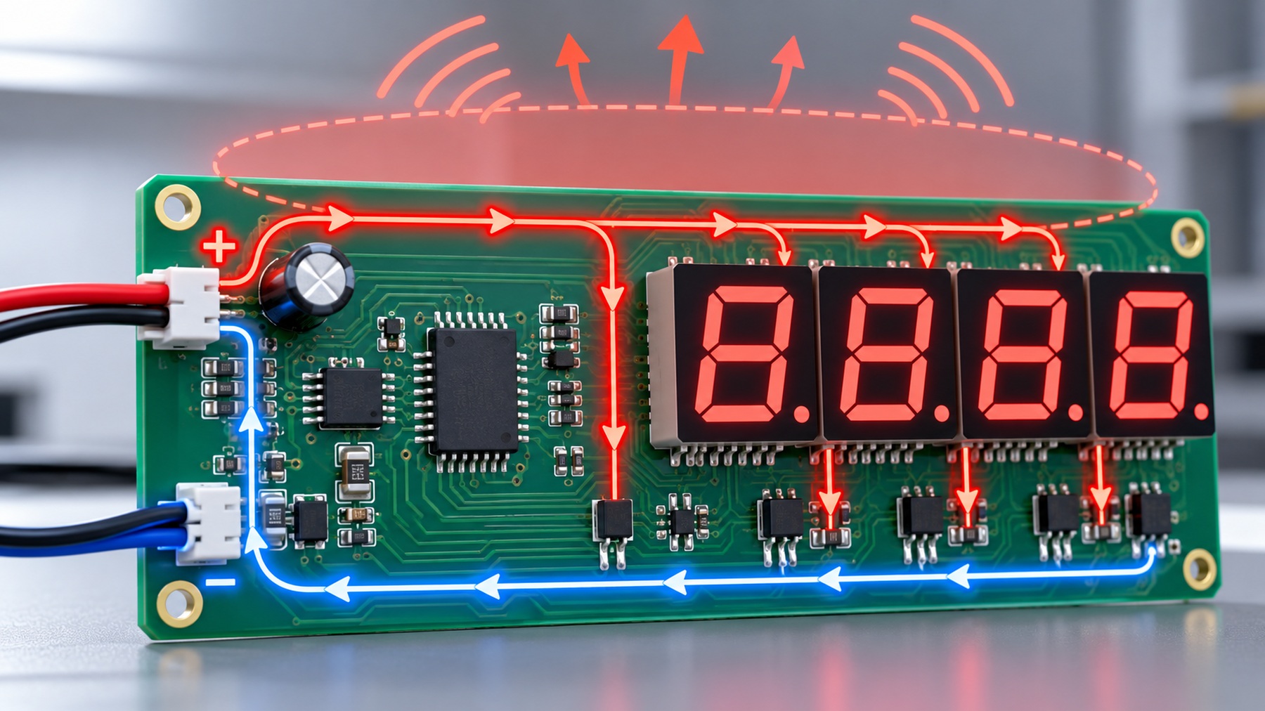
Where the power stage heats the enclosure, the display's own thermal margin shrinks. Brightness droop with temperature is a specification item, not a defect, and it should be quoted across the operating range rather than at a single ambient point.
Configuration Choices: Digit Height, Colour and Segment Count
Digit height, colour and segment count are usually decided together, because each one changes the others. A taller digit needs a larger window, which changes the seal perimeter; a colour change alters forward voltage and therefore the driver headroom.
Colour choice should follow the reading condition. Red and amber hold contrast against a dark background and are easy to dim, while white and blue can appear sharper at short distance but demand more careful current control to stay consistent across a multi-digit module.
Segment count follows from the information the charger must show: energy delivered, price, state of charge, connector status and fault codes rarely fit into four digits. Deciding the field layout before the module is specified avoids a late change from four digits to six.
Brightness uniformity across digits deserves an explicit limit in the specification. A charger showing three bright digits and one dim one reads as a fault even when the electronics are working correctly, and our explanation of LED display brightness in mcd sets out how to state that limit in a way a supplier can measure.
Integration Risks: Window, Cable and Firmware Timing
Three integration risks account for most late-stage display problems on charging equipment. The first is the window: an anti-reflective or tinted window specified for appearance can cost more contrast than the brightness increase it was meant to buy.
The second is the cable route. Ribbon or harness runs close to the power stage pick up switching noise, and a multiplexed display is sensitive to it; the symptom is faint ghosting on unselected digits rather than a hard failure, which makes it easy to misdiagnose as a display defect.
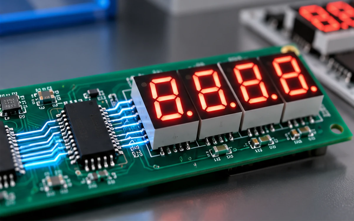
The third is firmware timing. Refresh rate, dimming method and blanking behaviour have to match what the display driver expects, and a mismatch shows up as flicker in a camera view or as visible scan artefacts at low dimming levels. Industrial LED display design reviews that ignore this interface tend to reopen the display specification late.
The Application & Form Factor Selection decision is therefore mostly about interface definition. Once the window aperture, viewing distance, brightness range and refresh behaviour are written down, the module choice becomes straightforward.
Supplier Input Checklist
Send the installation type, the viewing distance, the sun exposure direction, the enclosure internal temperature range and the information fields the display must show.
Add the window material and thickness, the available depth behind the front panel, the connector type and the drive scheme the controller supports. These five items decide more of the final specification than any single brightness number.
Finally, state the acceptance route: which sample stage is approved, which parameters are measured on the sample, and which limits apply to the production lot. Without that, the sample and the shipment are approved against different expectations.
Frequently Asked Questions
How to specify LED display for EV charger for an OEM application?
Start from the installation site and viewing distance, then derive digit height, brightness range and dimming depth from them. Add the window material, enclosure temperature range and required information fields before asking for a quotation.
Which parameters matter most for LED display for EV charger?
Contrast in direct sun, the dimming range at night and brightness uniformity across digits matter most, because each one is visible to the driver immediately. Sealing and thermal behaviour decide whether those three stay stable over the product life.
How to validate LED display for EV charger in the final product?
Validate in the real housing, behind the real window, at the highest and lowest expected ambient temperatures and at both full and minimum brightness. Check readability at the actual viewing distance in daylight and confirm there is no visible flicker or ghosting at low dimming.
What should engineers send a supplier for LED display for EV charger?
Send the drawing with window aperture and depth, the digit height and field layout, the brightness and dimming requirement, and the connector and drive scheme. A photograph of the installation site is also useful because it conveys the sun and glare conditions faster than a written description.
Does a brighter display always read better in sunlight?
No, because readability depends on contrast between lit and unlit areas rather than on absolute luminance. A very bright display behind a reflective window can read worse than a dimmer one with a darker background and a narrower emission window.
Conclusion: Specify the Site, Not Just the Module
An LED display for EV charger succeeds when the specification starts from the site: sun angle, viewing distance, night dimming, enclosure temperature and the information the driver has to read. Starting from a module datasheet tends to produce a display that passes a bench test and disappoints in a car park.
If you are specifying a display for a charging product and want the digit height, window and dimming scope reviewed against your enclosure, send the charger display scope to the HOUKEM team and we will confirm what applies to your design.
Custom LED Display Light Leakage: Segment Walls, Windows and Optical Isolation
LED Display Enclosure Window Alignment: A Mechanical Integration Guide