


7 Segment Display Current Consumption Calculation for Multi-Digit Designs

Quick Answer: Three Numbers, Not One
The calculation produces three separate figures. The first is the current through one segment. The second is the current through one digit, which is the segment current multiplied by the number of lit segments. The third is the average current the supply actually sees.
Confusing these three is the usual source of a supply that browns out under load. A driver is rated for peak current per output, a supply is sized for average current, and the wiring has to survive both.
Multiplexing adds the fourth ingredient. When digits are scanned, only one digit is driven at a time, so the average falls while the peak stays the same.
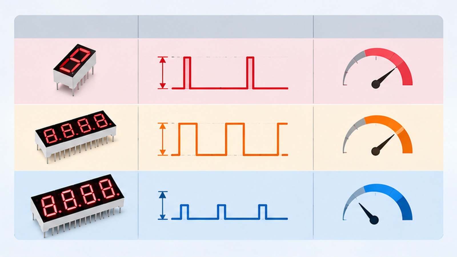
Segment Current: The Building Block
Segment current starts from the desired brightness and the device forward voltage. It is set by the series resistance or by a constant-current driver, and it should be chosen conservatively because it is the value everything else is derived from.
Once the segment current is fixed, the per-digit current follows directly. A digit showing the figure eight lights seven segments, so the digit current is seven times the segment current in that instant.
The single-device case is covered in our article on LED current limiting resistor calculation, and the multi-digit case simply extends it by counting lit segments.
Per-Digit Current and Why It Decides the Driver
Per-digit current is the peak figure the driver output has to handle. A sink driver for one digit must pass the sum of all lit segments without exceeding its rating or its thermal limit, and the switch family used for that output changes how much of the peak it can take, as our comparison of BJT and MOSFET driver choice for multiplexed displays explains.
This is the number that separates a workable driver from an overloaded one. Choosing a driver by the segment current alone understates the load by the number of lit segments, which is why a design can measure correctly on a single digit and fail on a full display.
Driver selection on that basis is treated in our article on 7 segment display driver IC selection, where the per-digit current is the first specification to match.
Multiplexing: From Peak to Average
In a multiplexed display each digit is driven for a fraction of the frame, and that fraction is the duty cycle. The average current the supply must deliver is therefore the peak current multiplied by the duty cycle, adjusted for the number of digits active at any moment.
Duty cycle changes the appearance as well as the arithmetic. A shorter duty cycle reduces the average and can reduce perceived brightness unless the peak is raised to compensate, and raising the peak has its own limit.
That trade-off between peak and average is described in our article on 7 segment display PWM dimming, and it uses the same two figures this budget produces.
Which Parameters Move the Number
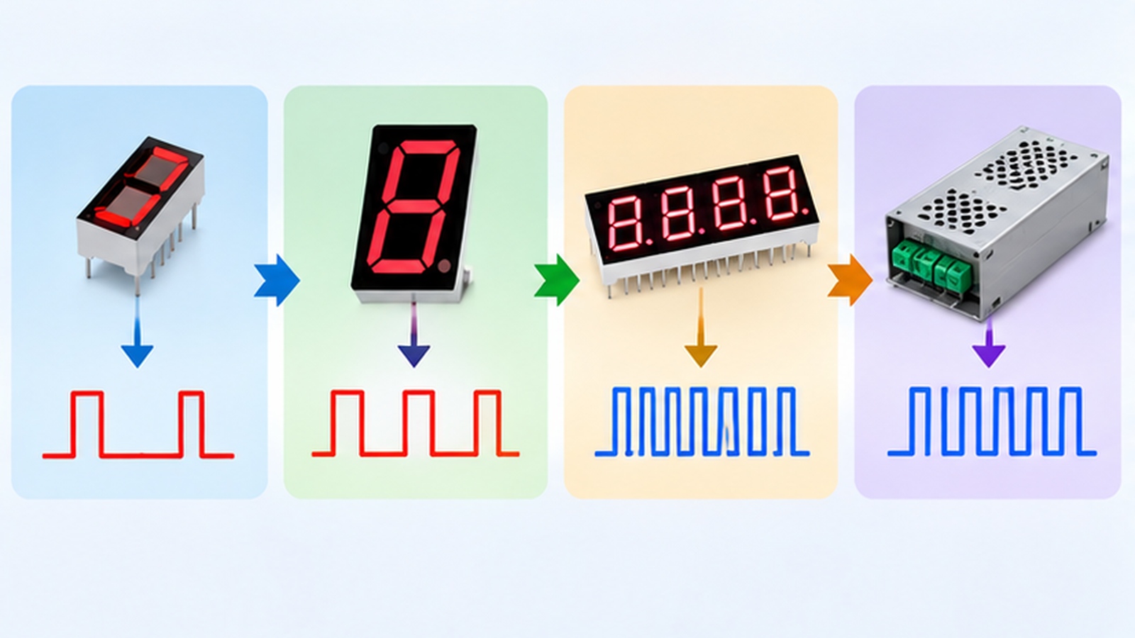
Only a handful of parameters actually change the result, and each one stresses a different limit.
| Variable | Effect on the budget | Limit it can breach |
|---|---|---|
| Segment current | Raises per-digit and average current in proportion | Driver output rating |
| Lit segments per digit | Raises per-digit peak without changing the segment value | Driver thermal limit |
| Digit count scanned | Lowers the duty cycle and the average for the same peak | Perceived brightness |
| Duty cycle | Scales the average current directly | Supply sizing and brightness |
| Forward voltage spread | Shifts the current if the drive is resistive | Digit-to-digit matching |
| Dimming | Reduces the average when applied by current rather than by pulse | Brightness consistency |
Reading the table as a list of independent choices is the mistake to avoid. Raising the peak to recover brightness increases per-digit current, while lengthening the duty cycle increases the average, and both move at once.
A Worked Budget in Five Steps
The sequence below produces the numbers needed to specify a supply and a driver, in an order that keeps each step checkable.
- Fix the segment current from the brightness target and the device forward voltage at the intended drive.
- Multiply by the maximum lit segments per digit to obtain the per-digit peak current.
- Convert to average using the multiplex duty cycle that the chosen refresh and digit count produce.
- Add the controller, the driver quiescent current and any indicator elements to the average.
- Compare the total against the supply rating with headroom, and the peak against the driver rating without it.
Step five is where a comfortable design becomes an uncomfortable one. A supply that meets the average with no margin will sag whenever the display updates, and that sag appears as a dimming or flicker symptom rather than as a current problem.
Frequently Asked Questions
How to evaluate 7 segment display current consumption calculation for an OEM design?
Start from the segment current, build the per-digit peak and then convert to a multiplexed average with the actual duty cycle. Compare the peak against the driver rating and the average against the supply rating.
Which parameters matter most for 7 segment display current consumption calculation?
The segment current, the lit segments per digit and the multiplex duty cycle decide almost the whole result. Forward voltage spread matters mainly when the drive is resistive rather than regulated.
How does 7 segment display current consumption calculation affect LED performance?
It sets the average current, and the average drives both brightness and junction temperature, which is why an underestimated budget shows up as early aging. It also decides whether the driver runs inside its thermal limit.
How should engineers validate 7 segment display current consumption calculation before production?
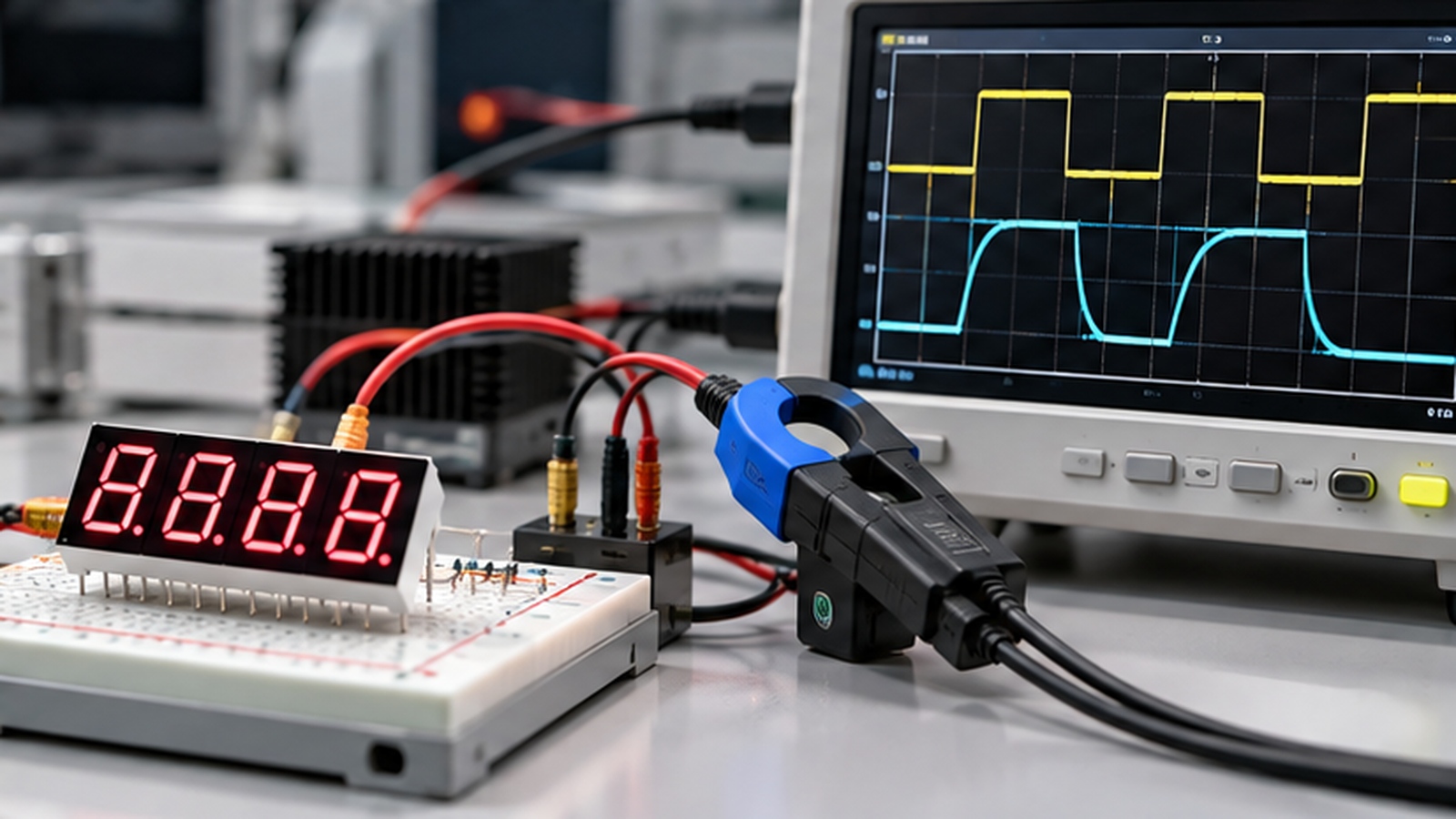
Measure the supply current on a full display showing the worst-case digit pattern, then compare it with the calculated average. Measure the per-digit line with a current probe and check the peak against the driver rating.
Does the worst case use the figure eight on every digit?
No, the worst case for the supply is the pattern that lights the most segments in total across the frame, while for the driver it is the digit with the most lit segments. 7-Segment Drive & Circuit Design uses both, because they stress different limits.
Conclusion: Size the Supply From the Average and the Driver From the Peak
A reliable 7 segment display current consumption calculation produces a peak figure and an average figure and uses each for the limit it stresses. Peak sizes the driver, average sizes the supply, and the duty cycle links them.
Worked in that order, 7 segment LED design stops depending on a rule of thumb, and multi-digit LED display design gains a number that can be measured and compared. Both figures should be re-measured at the worst-case pattern before production release.
If a display draws more than the budget allows and the cause is not yet clear, send the digit count, the drive method and the measured current through the inquiry page for engineering review.
BJT vs MOSFET 7 Segment Display Driver Choice for Multiplexed Designs


