


Common LED Failure Modes: Open Circuit, Short Circuit and Output Degradation

Quick Answer: Identify the Family Before the Cause
An open circuit removes the current path, a short circuit removes the voltage across the die, and degradation leaves both intact while reducing the light they produce. The three families produce different symptoms, they respond to different measurements, and they lead to different design corrections.
That is the reason the first step in any investigation is classification rather than root cause. Once the family is known, the candidate causes narrow to a short list, and only the measurements that appear in that list need to be taken.
The classification is also what decides the fix. An open circuit is usually a mechanical or assembly question, a short circuit is usually an electrical or contamination question, and degradation is almost always an operating-stress question that no component swap will settle.
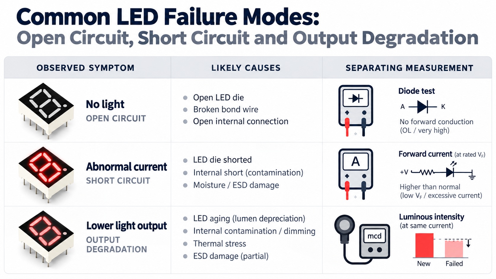
Open Circuit: The Current Path Is Gone
An open failure means current can no longer pass. In a wire-bonded emitter the usual location is the bond wire or its interface, and in an assembled product the same symptom appears when a solder joint, a pad or a connector contact has cracked. The distinction matters because the two have different remedies.
The symptom depends on the circuit. A single emitter or a single segment simply goes dark, while an open die inside a series string takes the whole string down with it. That behaviour is the reason a failed display can lose an entire digit rather than one element, and it is described from the drive side in our explanation of open-circuit behaviour in a string.
Mechanically induced opens are associated with thermal cycling and with assembly stress, because a joint that sees repeated expansion and contraction eventually fails at the weakest interface. The useful question is therefore not only where the break is, but whether the location points at a thermal design that needs attention, which is covered in our guide to thermal management.
Short Circuit: The Voltage Across the Die Collapses
A shorted die behaves differently. The current still flows, but it bypasses the junction, so the forward voltage across the affected element falls toward zero and no light is produced. In a multiplexed display the result is a segment or a position that stays dark while the rest of the panel looks normal, and in a series string it can pull the shared current away from the remaining devices.
The practical signature is measurable rather than visible. A device that reads close to zero volts in the forward direction, while a known good part from the same lot reads a normal forward voltage, is a short until something else is proven. Contamination, metallic debris and mechanical damage at the die attach are the usual routes, and all three are handling questions as much as design questions.
Because a short can be introduced after the electrical design is frozen, the finding belongs with the goods-in and process controls rather than with the schematic. How that evidence is collected is set out in our checklist for incoming inspection.
Output Degradation: Everything Works, Just Less Well
Degradation is the family that generates the most disagreement, because the product still functions. Output falls gradually, the change is small at first, and by the time it is visible the operating history that produced it is usually unavailable.
Three drivers account for most of the effect. Junction temperature is the strongest, because it accelerates the ageing of the die, the encapsulant and the phosphor system at the same time. Drive current is the second, since an emitter run above its intended operating point ages faster than one run within it, and the difference between the two ratings is explained in our comparison of forward current versus rated current. The third is the thermal path itself, and putting a number on it is the subject of our method for LED junction temperature calculation.
A degraded part is not a defective part until the operating condition has been checked. If the junction temperature in the finished enclosure is higher than the value used during qualification, the emitter was never the problem, and replacing it changes nothing.
Triage Table: Symptom to Measurement
The table below pairs each reported symptom with the measurement that separates the candidate causes in that row. It is ordered by the amount of equipment it needs, so the cheapest check comes first.
| Reported symptom | First measurement | What separates the causes |
|---|---|---|
| One element or digit completely dark | Continuity and forward-voltage check on the isolated element | No conduction suggests an open path; normal forward voltage with no light suggests a drive or connection fault |
| A whole series string dark | Forward voltage across each device in the string | One near-zero reading locates a short; one open reading locates the break |
| Position visibly darker than its neighbours | Optical output of that position against a neighbouring one at equal drive | Equal current with unequal output points to the device; equal output with unequal current points to the drive |
| Output lower than the qualification build | Steady-state case and junction temperature at the real duty cycle | A temperature above the qualified value explains the loss without a device defect |
| Failure appears after thermal cycling | Inspection of joints, pads and bond interfaces | A crack or lifted interface points to mechanical stress rather than to the die |
Working through the rows in order prevents the most common error in failure work, which is to replace the component before the operating condition has been measured. It also keeps the finding in the purchasing record, because every row produces a number rather than an opinion.
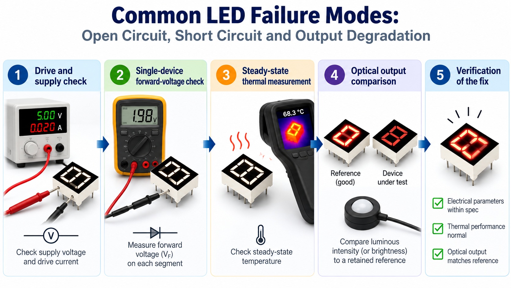
Isolating the Cause in Five Steps
The sequence below is deliberately arranged so that each step either resolves the question or narrows it. It assumes the suspect unit is available and can be measured.
- Confirm the drive. Verify the supply, the current-setting element and the switching stage at the affected position before touching the emitter, because a drive fault reproduces a device symptom exactly.
- Measure the isolated device. Remove it from the shared current path and record the forward voltage and the emitted output at a defined current.
- Measure the temperature. Let the product reach steady state at its real duty cycle and record the case temperature, then compare it with the value used during qualification.
- Compare against a reference. A retained sample from the approved build is the only reliable baseline; a datasheet typical value is not.
- Reproduce after the correction. Apply the intended fix and repeat the same measurements under the same conditions, so the result is comparable with the original finding.
Step four is where informal investigations usually break down. Without a retained reference, a small output difference cannot be attributed to ageing, and the investigation stalls on opinion. Recording the reference at approval time is therefore a reliability activity, not a documentation formality.
Frequently Asked Questions
What causes problems related to LED failure modes?
Operating stress, mechanical stress and handling damage cover most cases, with junction temperature the single strongest driver of gradual degradation. Contamination and assembly stress account for a large share of the abrupt open and short failures.
How to troubleshoot LED failure modes in an LED design?
Confirm the drive first, then measure the isolated device and the operating temperature before replacing anything. Compare the result against a retained reference sample rather than against a datasheet typical value.
Which measurements help diagnose LED failure modes?
Forward voltage on the isolated device separates open from short failures, while optical output at a defined current separates a degraded device from a drive fault. Steady-state case temperature at the real duty cycle explains most gradual losses.
How to verify the fix for LED failure modes before production?
Reproduce the original condition and repeat the same measurements, so the before and after numbers come from the same setup. Then run the corrected condition at the operating extremes before releasing it.
Is every dark element a failed LED?
No, because a drive fault, a broken connection or a damaged soldered joint produces the same appearance while the emitter is intact. Measuring the isolated device is what separates the two.
Conclusion: Classify, Measure, Then Correct
LED failure modes are easier to work with once they are treated as three families rather than one symptom. Classify the failure, take the measurement that belongs to that family, and the design correction follows from evidence instead of assumption.
The same discipline makes LED reliability engineering, LED thermal design and Reliability & Failure Analysis inputs verifiable, because every finding carries a condition, a number and a reference. That is what allows a repeat failure to be recognised as a repeat, and a design change to be justified before it reaches production equipment.
If a failure cannot be settled in house, send the measurements and the operating condition through the inquiry page so the engineering team can review the configuration against the recorded evidence.
LED Viewing Angle vs Beam Angle: What Datasheets Actually Mean


