


LED Viewing Angle vs Beam Angle: What Datasheets Actually Mean

Quick Answer: One Is a Threshold, One Is a Convention
Viewing angle is a threshold: it is the total angle over which the emitted intensity stays above a defined fraction of its on-axis value. Beam angle is a convention: it describes how much of the total output falls inside a chosen boundary.
Because the two definitions ask different questions, they produce different numbers for the same emitter, and the gap widens as the beam becomes narrower and the tails become longer.
The practical rule is to identify which definition the number came from before comparing it with anything, and then to write the same definition into the requirement so that a later measurement can reproduce it.
How Viewing Angle Is Defined and Measured
The threshold definition is the one most commonly used on emitter datasheets, and it is usually expressed as the angle at which intensity falls to half of the on-axis value.
The figure depends on the reference axis, which is normally the mechanical centre of the package but is sometimes the optical axis of the lens inside it. A part mounted or measured off that axis reports a different angle even when the radiation pattern is unchanged.
It also depends on the measurement geometry. An angle measured in the far field describes the emitter as a point, while a measurement taken close to the device includes the physical size of the emitting area and produces a wider figure. Two laboratories can therefore disagree without either being wrong, which is why the condition belongs in the record.
Reading the value in the context of the other parameters on the same page is the habit that prevents most mistakes, and the fields that carry the condition are reviewed in our guide to reading LED specifications.
How Beam Angle Differs in Practice
Where the visibility of an emitter on a screen is judged by what a person can see, designers also think in terms of the photometric pair, and the argument for separating intensity from flux is set out in our explanation of luminous intensity compared with luminous flux. The same distinction explains why an angular figure quoted against an intensity threshold is not a containment figure.
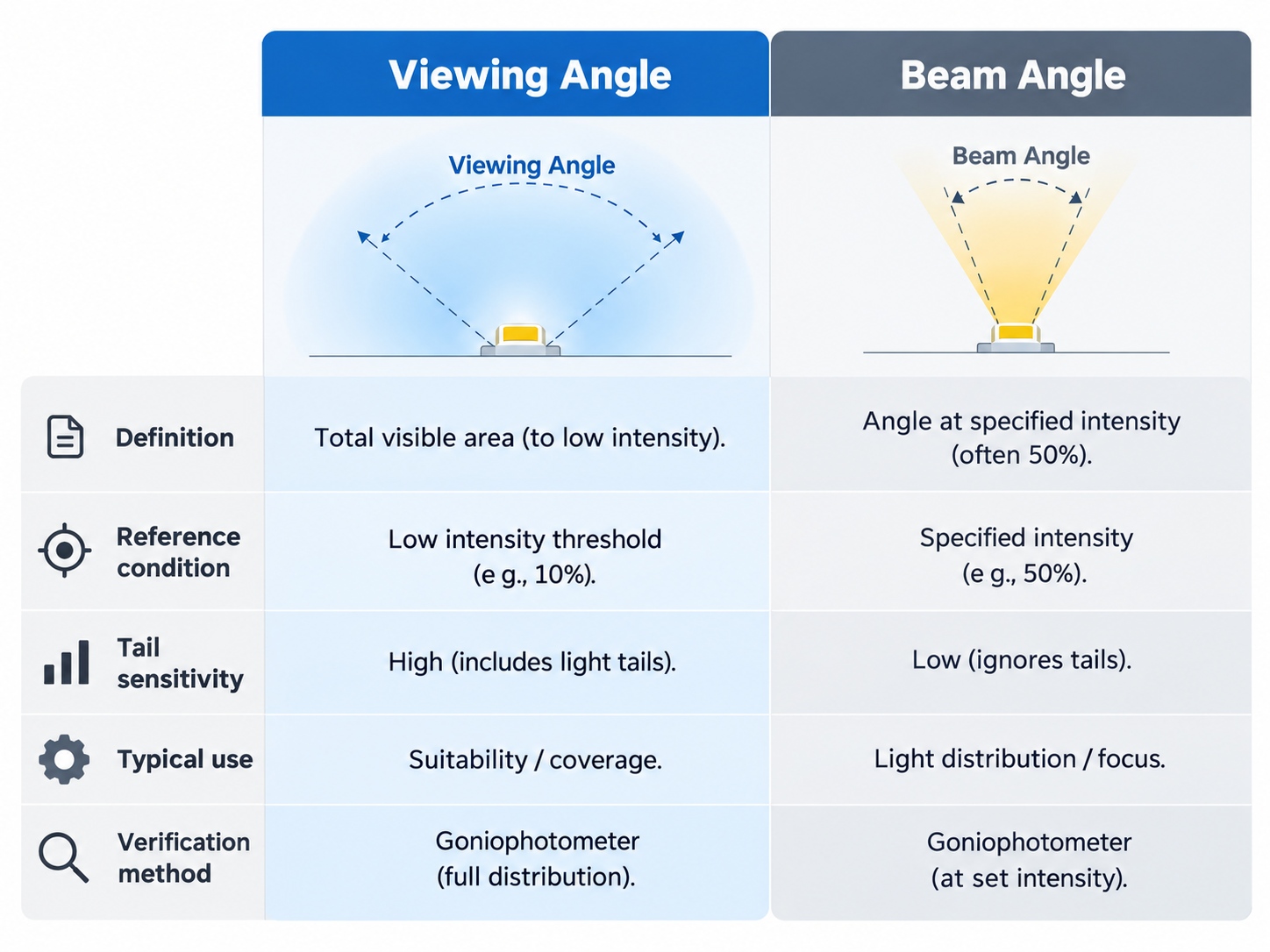
The table below compares the two conventions on the points that decide whether they can be substituted for each other.
| Question | Viewing angle | Beam angle |
|---|---|---|
| What is being defined | A threshold on the intensity distribution | A boundary containing a share of the output |
| Typical reference condition | Half of the on-axis intensity | A stated percentage of total radiant power |
| Effect of narrow beams | Falls quickly as the pattern narrows | Usually wider for the same emitter |
| Sensitivity to the tails | Low, because the tails sit below the threshold | High, because long tails add contained energy |
| Best used for | Reading angle and visibility limits | Energy delivered into a target area |
| Verification method | Angular intensity scan about the reference axis | Angular scan integrated against a defined boundary |
Reading the table as a pair rather than as two alternatives is what makes the difference useful. The threshold figure answers whether a receiver can see the emitter, and the containment figure answers how much energy reaches a surface.
Why the Same Emitter Gets Two Different Numbers
A radiation pattern is a continuous distribution, and any single angle is a summary of it. Different summaries give different numbers, and the choice of summary usually follows from what the supplier expects the buyer to do with it.
Emitters intended for indication tend to be described with the threshold figure, because the buyer is usually working with visibility. Emitters intended to deliver energy tend to be described with a containment figure, because the buyer is usually working with irradiance at a plane. The same package can appear in both conversations under different headings.
Lens design adds a second source of divergence. A secondary optic shapes the pattern and moves energy between the centre and the tails, which changes the two summaries by different amounts. A lens that makes a beam more uniform may leave the threshold figure almost unchanged while moving the contained energy considerably.
For infrared emitters the effect is particularly visible, because a narrower pattern concentrates the same output into a smaller solid angle and raises the on-axis figure. The relationship between that concentration and the angular width is described in our explanation of IR LED radiant intensity, and it explains why a narrow emitter can appear more capable than a wide one at the same drive current.
Specifying the Right Angle for a Design
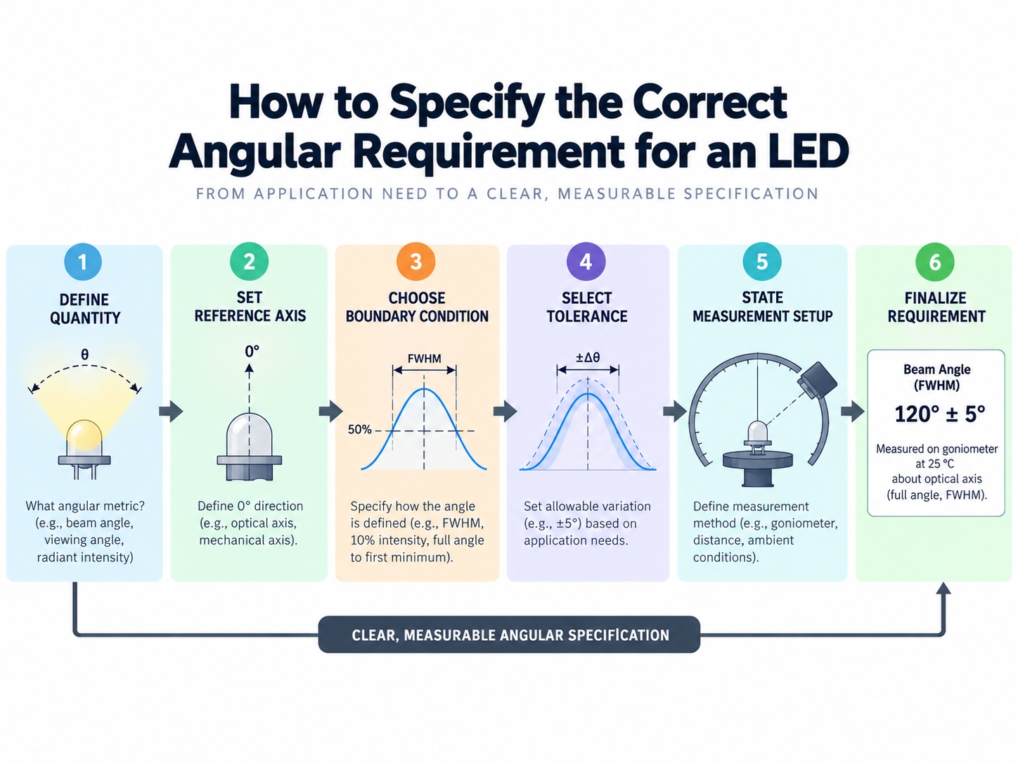
The requirement should name the quantity, the reference condition and the geometry, in that order.
- Name the quantity and the definition, so that the number has a stated meaning rather than a common-sense one.
- Name the reference axis and the measurement distance, so that the figure can be reproduced on a different bench.
- Name the boundary condition for a containment figure, or the threshold fraction for a visibility figure.
- Name the acceptance tolerance, because an angular figure without a tolerance cannot be accepted or rejected.
Two failures appear repeatedly at this stage. The first is a requirement that quotes an angle without saying which definition was used, which produces a number that two suppliers can interpret differently and both satisfy. The second is a requirement that transfers a containment figure into a visibility application, which usually results in a display that is specified correctly and still unreadable at the sides.
For display work the second failure is the more expensive, because readability is judged across the whole panel rather than at one point. The relationship between an angular figure and apparent brightness in a display context is covered in our article on display brightness ratings, which is where the acceptance criterion normally ends up.
Frequently Asked Questions
How to evaluate LED viewing angle vs beam angle for an OEM design?
Identify what the requirement is really about: visibility at an angle, or energy delivered into an area. Then choose the figure whose definition matches that question and write the reference condition beside it.
Which parameters matter most for LED viewing angle vs beam angle?
The definition of the figure matters most, followed by the reference axis and the measurement distance. Without those three, two readings of the same emitter cannot be compared and neither can be reproduced.
How does LED viewing angle vs beam angle affect LED performance?
Neither angle changes how much light the emitter produces, because they describe how that output is distributed. They do change how much of it reaches a receiver, which is why the wrong choice affects the application rather than the part.
How should engineers validate LED viewing angle vs beam angle before production?
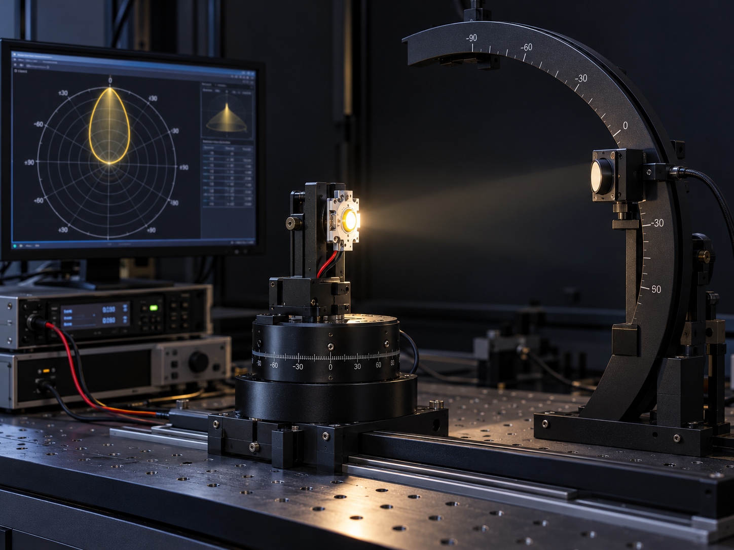
Measure the angular distribution on the intended assembly using the reference condition stated in the requirement, and confirm the result at the extremes of the production tolerance. A single on-axis measurement does not confirm an angular specification.
Can the two angles be converted?
Not reliably without the full radiation pattern, because the conversion depends on the shape of the tails rather than on the two numbers alone. Where both figures are needed, they should be requested together under a stated method rather than derived from one another.
Conclusion: Write the Definition, Not the Number
LED viewing angle vs beam angle is settled by naming the definition before the value. Once the threshold fraction or the containment boundary is written down, the number becomes reproducible and the comparison between suppliers becomes meaningful.
The approach also makes Optical Parameters & Measurement work auditable, because LED optical measurement and LED datasheet parameters are then recorded together with the geometry they were taken under. That is what allows a supplier, a laboratory and an incoming inspection function to agree on the same result.
If you are writing an angular requirement for an indicator, a display or an emitter and want the measurement condition and lens options confirmed for the application, review the HOUKEM LED product range and send the requirement through the inquiry page.
Photometric vs Radiometric LED Measurement: Lumens, Candela and Watts


