


LED Driver Current Ripple: How Ripple Reaches the Light Output

This guide covers where LED driver current ripple comes from, which parameters set its size, how to budget it before the board is laid out, and how to verify it before a design is released to production.
Quick Answer: What LED Driver Current Ripple Actually Is
Ripple is the peak-to-peak variation of the output current around its regulated average, expressed either in milliamps or as a percentage of the average. A driver set to a given current with a twenty percent ripple delivers a peak above that value and a trough below it on every switching cycle.
The distinction matters because the emitter responds to both ends of the trace. The peak drives instantaneous flux and local heating, the trough drives the minimum, and the average is what a DC meter reports. A design reviewed only against the average can look correct and still produce a brightness variation, an efficiency penalty or a measurement disagreement that is hard to trace later.
Where Ripple Comes From
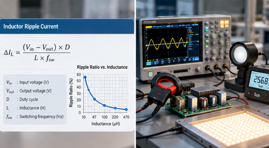
In a switching constant current driver the dominant term is the inductor current ramp. During the on time the current rises, during the off time it falls, and the difference is set by the voltage across the inductor, the inductance and the switching frequency. The output capacitor then removes part of that ramp, and how much it removes depends on its capacitance and, more importantly, on its equivalent series resistance.
In a linear regulator the output is quiet by construction but the ripple moves to the input side and to thermal dissipation instead, which changes the problem rather than removing it. Hysteretic and ripple based controllers sit between the two: they regulate on the ripple itself, so the ripple is a design parameter rather than a defect.
Layout adds a second, often overlooked component. The loop formed by the switching cell, the input capacitor and the return path radiates and couples into the current sense line, so a driver that measures cleanly on a bench fixture can show additional high frequency content once it is inside the product enclosure. That content is usually small in amplitude and large in measurement consequence.
The control loop itself contributes at low frequency. A driver with modest bandwidth takes time to correct a load step, and the resulting excursion appears as a slow envelope rather than a switching frequency ripple. Both are ripple in the practical sense, and they should be specified separately because they are fixed by different parts of the circuit. The reason a regulated current is required at all is set out in our note on why LEDs require constant current control.
Governing Parameters and What They Change
Four parameters decide most of the ripple budget: the voltage across the inductor during each phase, the inductance, the switching frequency and the output capacitance with its series resistance. Change one and the others have to move, which is why ripple is a budget decision rather than a component decision.
| Parameter | Effect on ripple | What to verify |
|---|---|---|
| Inductance | Ripple falls as inductance rises for a fixed frequency | Saturation current at the peak value, not the average |
| Switching frequency | Ripple falls as frequency rises, with a matching loss increase | Driver thermal rise and EMI behaviour at the chosen frequency |
| Output capacitance and ESR | Capacitance sets the charging swing, ESR sets the step | ESR at the switching frequency, not the 100 Hz value |
| Input and output headroom | Low headroom shortens the off time and raises the ripple ratio | Margin at minimum supply and maximum forward voltage |
| Sense resistor tolerance | Shifts the average, so a percentage ripple moves in absolute terms | Sense tolerance across temperature, not only at 25 C |
| Load capacitance and wiring | Cable inductance slows the current edge and can add ringing | Behaviour with the real harness length, not a short bench lead |
Two of these are frequently checked against the wrong quantity. An inductor is often selected on its nominal rating when the relevant figure is the saturation current at the peak of the ripple, and a capacitor is often selected on its 100 Hz capacitance when the relevant figure is its impedance at the switching frequency. Both mistakes leave a design that measures well in a datasheet comparison and poorly on the bench.
Budgeting Ripple Before the Board Is Laid Out
Start from the acceptable ripple ratio and work backwards. For a buck-derived constant current stage the peak-to-peak inductor ripple is proportional to the output voltage across the inductor during the off time, and inversely proportional to inductance and switching frequency. Fix two of the three and the third is determined.
The practical order is to fix the switching frequency from the EMI and loss budget, choose the inductance that meets the ripple target at the worst case duty cycle, then add output capacitance only for the residual that the inductor cannot remove. Adding capacitance first usually produces a larger, more expensive board for the same result.
Worst case is not the nominal operating point. Ripple is highest where the duty cycle is furthest from the value that minimises it, which usually corresponds to the extremes of the input supply range combined with the extremes of forward voltage tolerance. Evaluate both ends, because a design that passes at nominal can exceed the limit at the low end of the supply window.
Dimming changes the calculation. Analog dimming reduces the average and leaves the ripple ratio roughly intact, while PWM dimming introduces a second, much lower frequency component whose amplitude is the full on current. The two are often confused in specifications, and the distinction between a duty-cycled rating and a DC rating is covered in our guide to LED pulse current versus continuous current.
Engineering Trade-offs: Efficiency, Size and Noise
Every route to lower ripple costs something. More inductance costs board area and copper resistance, higher frequency costs switching loss and can worsen radiated emissions, and more capacitance costs space and inrush. The right answer depends on which of those three the product is actually short of.
Headroom is the trade-off most often missed. A driver that regulates cleanly with generous input headroom can lose regulation margin when the supply is reduced to save system cost, and the visible result is a ripple increase that appears at the same time as a brightness change. Keeping the compliance voltage margin explicit prevents the two from being diagnosed as separate faults.
Ripple is fixed by choices made in three places: the topology, the magnetics and the layout. Those choices belong to LED driver design as a whole rather than to a single component, and a constant current LED design that treats ripple as a datasheet parameter rather than as an outcome usually revisits the question late. The resulting limits sit in the LED Driver & Power Design section of the specification, next to the current and voltage figures they modify.
For emitters with a steep current to flux relationship, a given ripple produces a larger relative flux variation than the same ripple would on a flatter emitter, and the effect is stronger at high drive currents where thermal modulation adds to the electrical one. That is why the acceptable ripple for a display emitter and for a curing array are not the same number even when both are driven at a regulated current.
Where the driver also serves UV or IR emitters, the constraint set widens. Peak current affects radiant output and junction temperature, and the measurement instrumentation may integrate over a window that hides or exaggerates the modulation, which is why the driver guidance in choosing a driver for UV and IR LEDs treats ripple as part of the optical specification rather than as an electrical detail.
Verification: Bench Measurement and Specification Checklist
Measure current, not voltage across the sense resistor alone, and measure it with a probe whose bandwidth exceeds the switching frequency by a comfortable margin. A probe that is too slow reports a clean waveform by averaging the content that matters.
Take the measurement at the emitter terminals rather than at the driver output, with the production harness length in place. The difference between the two points is exactly the part of the ripple that the layout and the wiring contribute, and it is the part most likely to change between the bench and the product.
Record the average, the peak-to-peak value and the frequency of the dominant component, at minimum and maximum supply, at the temperature extremes and at both ends of the dimming range. A single measurement at nominal conditions is not a validation, and it will not survive a design review.
Finally, write the specification in a form a supplier can accept: a maximum ripple ratio, a frequency band over which it applies, the measurement point and the test conditions. Ripple limits quoted without a measurement point are not comparable between two drivers, and the limits that matter for the emitter itself are set out in LED forward current versus rated current. For low current indicator designs where the driver is a resistor, the same budgeting logic applies in the LED current limiting resistor calculation, with supply tolerance replacing switching ripple as the dominant term.
Frequently Asked Questions
How to evaluate LED driver current ripple for an OEM design?
Evaluate it from the emitter backwards: fix the acceptable flux variation, convert that to a current ripple ratio, then check the driver against it at the worst case duty cycle and temperature. The measurement should be taken at the emitter terminals with the production harness.
Which parameters matter most for LED driver current ripple?
Inductance, switching frequency, output capacitance with its series resistance, and the available headroom matter most. Sense resistor tolerance also matters because it shifts the average the ripple is a percentage of.
How does LED driver current ripple affect LED performance?
It modulates flux and junction temperature around the average operating point, which shows up as brightness variation, a small efficiency change and a measurement that disagrees with a DC reading. At low frequencies it can also become visible flicker.
How should engineers validate LED driver current ripple before production?
Validate with a current probe at the emitter, at minimum and maximum supply, at temperature extremes and across the dimming range, recording average, peak-to-peak and dominant frequency. The result should be compared against a written limit that names the measurement point.
Is PWM dimming ripple the same as switching ripple?
No, PWM dimming adds a low frequency on and off component whose amplitude is the full drive current, while switching ripple sits on top of the on state at the converter frequency. They are specified separately and fixed by different parts of the circuit.
Conclusion: Specify Ripple the Way You Specify Current
LED driver current ripple is decided by four parameters and confirmed by one measurement taken in the right place. Treated as a side effect, it surfaces later as a brightness complaint, a failed comparison between two builds, or a disagreement between a meter reading and a visual assessment.
If you are defining a driver specification for a custom LED display or emitter and want the ripple limit, measurement point and test conditions reviewed against your own design, send the driver specification to the HOUKEM team and we will confirm what applies to the part you are sourcing.
LED Driver Compliance Voltage: Why Current Regulation Drops Out


