


LED Rise Time Fall Time: How Pulse Fidelity Is Decided

Quick Answer: When the Edge Matters
The edge matters whenever the pulse is short relative to the transition, or whenever a receiver is sensitive to the edge rather than to the average. If the pulse is long and the detector is slow, the transition is irrelevant.
The test is a ratio rather than an absolute value. When the transition occupies a meaningful part of the pulse width, the pulse loses amplitude, shifts its apparent timing or spreads in a way that changes the measurement.
Three applications run into this first. Pulse-encoded sensing, high-frequency dimming and optical encoders all care about the edge, while general illumination usually does not.
What Rise Time and Fall Time Describe
Rise time is the interval between two defined levels on the leading edge, and fall time is the same interval on the trailing edge. The levels are stated as a percentage of the final value rather than being left implicit, because the interval depends on the definition.
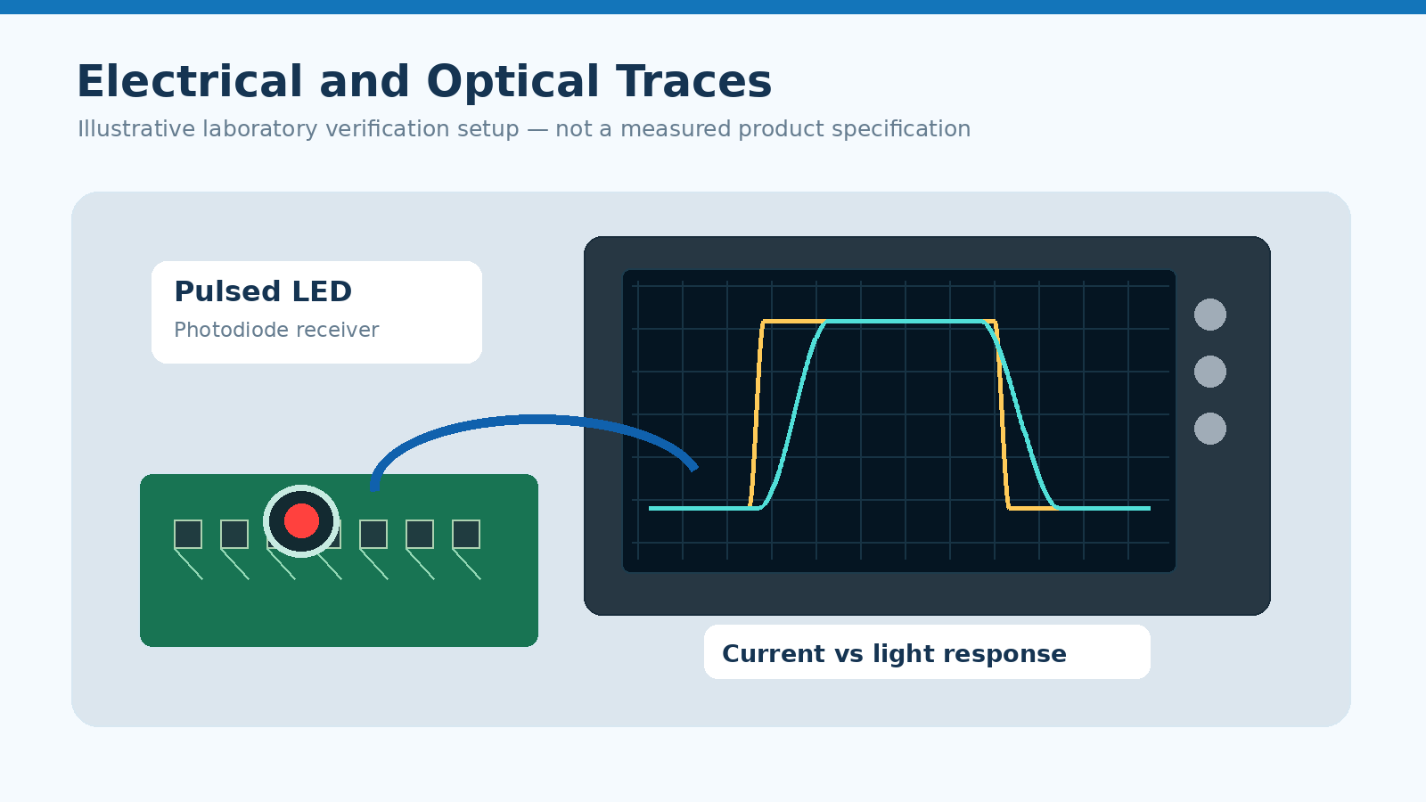
The measured edge also has two forms. The electrical edge is the current through the device, and the optical edge is the light it emits, and the two are not identical even though they are closely related.
The difference between the two is what separates a driver problem from a device problem, and it is also why the two are checked separately. LED Electrical Design & Derating treats the electrical edge as a circuit property first and a device property second.
What Sets the Limit
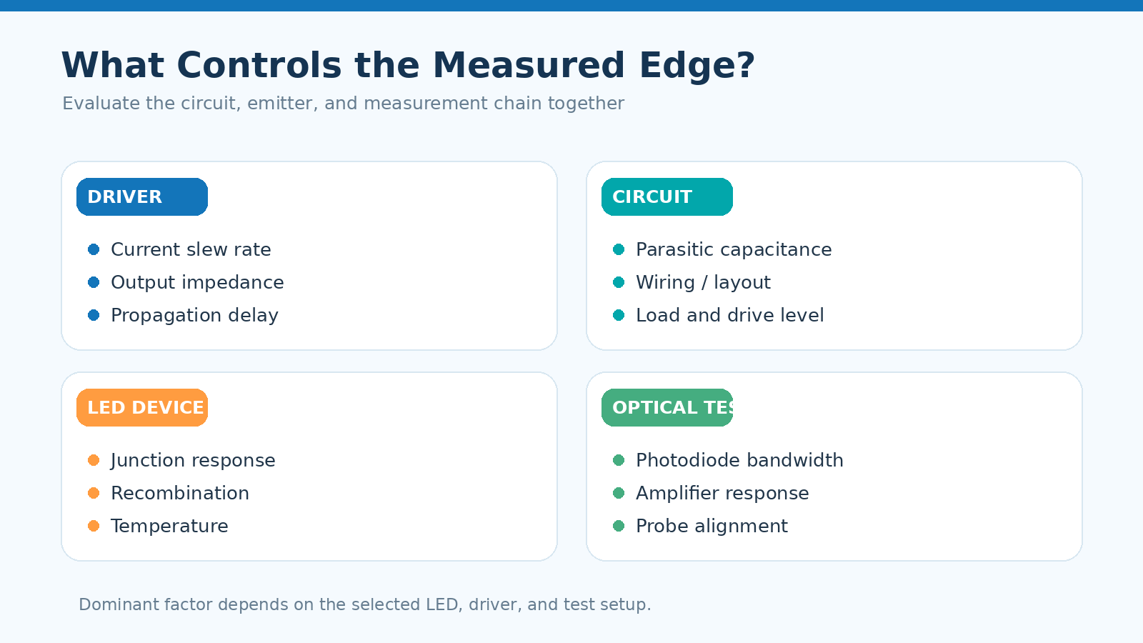
Electrical contributors and optical contributors act together, and knowing which dominates is what makes a design change effective.
| Contributor | Type | Usual dominance |
|---|---|---|
| Driver output slew | Electrical | Dominant when the driver is slow or current-limited |
| Wiring and trace inductance | Electrical | Dominant in long or high-current pulse runs |
| Junction capacitance | Electrical | Significant at very short pulses |
| Carrier recombination | Optical | Sets the floor for the optical edge |
| Phosphor response | Optical | Dominant in phosphor-converted emitters |
| Detector bandwidth | Measurement | Dominant when the receiver is slower than the emitter |
The last row is the one most often mistaken for a device limit. A measured edge that is slower than expected may be reporting the receiver rather than the emitter, which is why the verification sequence in the next section measures both.
The relationship between a short pulse and the current it is allowed to carry is described in our article on LED pulse current versus continuous current, and that arithmetic assumes the pulse actually has the intended shape. The distinction between a continuous operating rating and a short-duration rating is set out in our article on LED forward current versus rated current.
How the Edge Changes Performance
A slow edge reduces the energy delivered in a short pulse, which shows up as lower output rather than as an obvious failure. In a sensing system that reduction becomes a shorter detection range or a weaker return signal.
It also shifts timing. If a system measures the interval between a pulse and its return, an edge that differs between rise and fall introduces a timing error that no amount of averaging removes.
In dimming, the edge sets the practical upper limit on the modulation rate. Beyond that limit the dimming range compresses, which is the behaviour described in our article on 7 segment display PWM dimming.
Verifying the Edge Before Production
Verification should separate the contributions, because each has a different remedy.
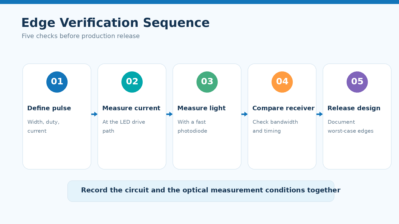
- Define the pulse in terms of width, duty and level, and state the rise-time definition to be used.
- Measure the current edge with a probe at the device, so wiring effects are included rather than hidden.
- Measure the optical edge with a detector whose bandwidth is known to exceed the emitter.
- Compare the two edges to decide whether the driver or the emitter is setting the limit.
- Confirm the receiver still meets its own timing budget with the measured edge, then release.
Step four is the decisive one. If the current edge is fast and the optical edge is slow, the emitter is the limit and a driver change will not help. If both are slow, the circuit is the limit and the device may be well inside its specification. Where the pulse is used for IR or UV sensing, the timing requirements a driver has to meet are gathered in our guide to LED driver selection for UV and IR LEDs.
Frequently Asked Questions
How to evaluate LED rise time fall time for an OEM design?
Compare the transition with the shortest pulse the design must carry, and treat the edge as significant when it occupies a meaningful share of that pulse. Then measure the current edge and the optical edge separately to see which one dominates.
Which parameters matter most for LED rise time fall time?
The driver slew, the inductance in the pulse path and the emitter recombination behaviour matter most. In phosphor-converted emitters the phosphor response usually sets the optical edge.
How does LED rise time fall time affect LED performance?
A slow edge reduces the output delivered in a short pulse and shifts the apparent timing of the pulse. In dimming it compresses the usable modulation range rather than causing an outright failure.
How should engineers validate LED rise time fall time before production?
Measure the current edge at the device and the optical edge with a fast detector, then confirm the receiver still meets its timing budget with the measured edge. Repeat at the temperature extremes of the application.
Can a fast LED fix a slow measured edge?
No, because the measurement itself may be limiting the result if the detector is slower than the emitter. The detector bandwidth should be established before any conclusion is drawn about the LED.
Conclusion: Treat the Edge as a Design Input
LED rise time fall time is only interesting when the pulse is short, but in those designs it decides whether the pulse carries the energy and the timing the system expects. Measure the current edge and the optical edge separately, and the limit becomes visible.
Handled as a design input, LED electrical design stops relying on steady-state numbers for a pulsed job, and the wider LED engineering guide gains a measured basis for the modulation rate. The same measurements should be repeated wherever the application runs at its temperature extremes.
If a pulsed design is short of output or short of timing margin and the cause is unclear, send the pulse definition and the measured edges through the inquiry page so the engineering team can review the configuration.
Common LED Failure Modes: Open Circuit, Short Circuit and Output Degradation


