IR LED Battery Energy Budget: Turning Pulse Current Into Operating Time

Quick Answer: Peak Current Does Not Decide Runtime
Battery life is set by charge consumed per unit time, so a 1 A pulse held for one twentieth of the period draws the same average as a continuous 50 mA, before conversion losses, which is why a pulsed IR battery life estimate that starts from the peak figure runs long. Build the budget from three quantities: peak pulse current, the fraction of time that pulse is on, and the efficiency of the stage that converts battery voltage into the forward voltage the emitter needs. Everything else in this article refines those three numbers.
From Pulse Waveform to Average Current
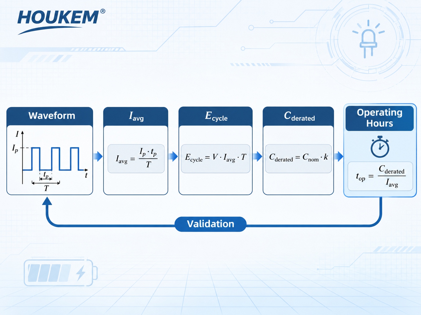
Start from the waveform rather than the rating. Record pulse amplitude, pulse width and repetition period, then multiply amplitude by pulse width to get the charge of one pulse. Dividing that charge by the period gives the average current the battery actually supplies, which is the IR LED average current that matters, and multiplying by the period again gives energy per cycle once the drive voltage is known. When the emitter is driven through pulse current rather than continuous current, both the amplitude and the duty profile have to be quoted together, because neither alone describes the load.
Two habits keep this step honest. First, measure the waveform at the emitter, not at the microcontroller pin, since series resistance and driver drop reshape the pulse. Second, keep the pulse shape you will ship as a design parameter, because firmware that changes the repetition rate changes the budget without changing anything on the schematic.
Adding Driver Conversion Losses
The battery supplies more charge than the emitter consumes, and the difference is the efficiency of the driver stage. A linear path dissipates the surplus voltage as heat at a current equal to the emitter current, while a switching path trades that loss for switching losses that scale with frequency. Express the result as an energy figure in milliwatt-hours or joules per cycle so that a duty change can be evaluated without rebuilding the whole model.
IR emitters frequently need a forward voltage well above a single lithium cell, which forces a boost stage and makes the input current larger than the emitter current by the voltage ratio divided by efficiency. That step is where many estimates lose their margin, because the input current is what stresses the battery, the protection circuit and the connector.
How Battery Capacity Should Be Discounted
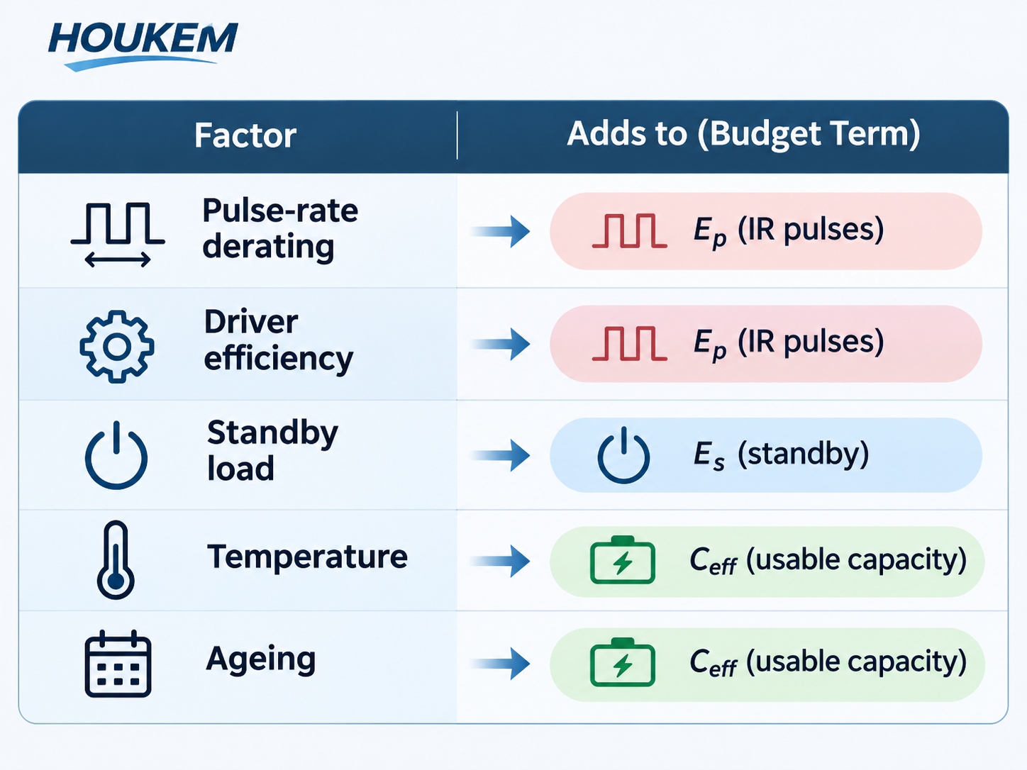
Nameplate capacity is measured under a reference discharge that rarely matches a pulsed load. Derating is therefore a deliberate design choice rather than a pessimistic habit: high-rate pulses depress delivered capacity, cold temperatures reduce it further, and a cut-off voltage that protects the system may strand charge that remains chemically available. Budget the usable fraction explicitly, and state the temperature and cut-off condition it applies to.
| Loss or effect | How it shows up | What to do in the budget |
|---|---|---|
| Pulse-rate derating | Less capacity is delivered at high discharge rates than the nameplate figure | Apply the derating for your pulse rate; confirm it from the cell datasheet rather than assuming a flat percentage |
| Driver efficiency | Input current exceeds emitter current by the voltage ratio | Divide emitter energy by measured efficiency at the operating point, not the peak figure |
| Regulator and standby load | A quiescent current that never switches off | Add it as a continuous term in parallel with the pulsed term |
| Temperature | Capacity and internal resistance both move at the temperature extremes | Run the budget at the coldest operating temperature the product promises |
| Ageing | Capacity fades over the service life | Decide whether the target is first-cycle runtime or end-of-life runtime |
Standby and Housekeeping Loads
In a duty-cycled product, the emitter may consume less than the electronics that surround it. A receiver front end, a comparator, a low-dropout regulator and a wake-up timer all draw current while the emitter is off, and their contribution is continuous rather than pulsed. Add these terms separately, then check the split: if the housekeeping term dominates, improving the emitter's duty profile will not move the runtime much, which is a useful finding before any redesign starts.
The Duty Profile Is a Commercial Decision
Where the emitter is a high-power device, the pulse amplitude and duration also set the thermal load, and the thermal design constrains how hard the emitter can be pushed. For products that need the larger emitters, the selection and drive trade-offs are summarised in the guide to high power IR LED selection, drive current and thermal design, and the beam side of the same link is covered by the IR LED polar radiation pattern reference. Both interact with the energy budget: a wider beam covers more of the field at the same energy, and a narrower one may allow shorter pulses but demands better alignment, so the IR illumination power budget and the optics have to be settled together rather than in sequence.
Validating the Estimate on Hardware
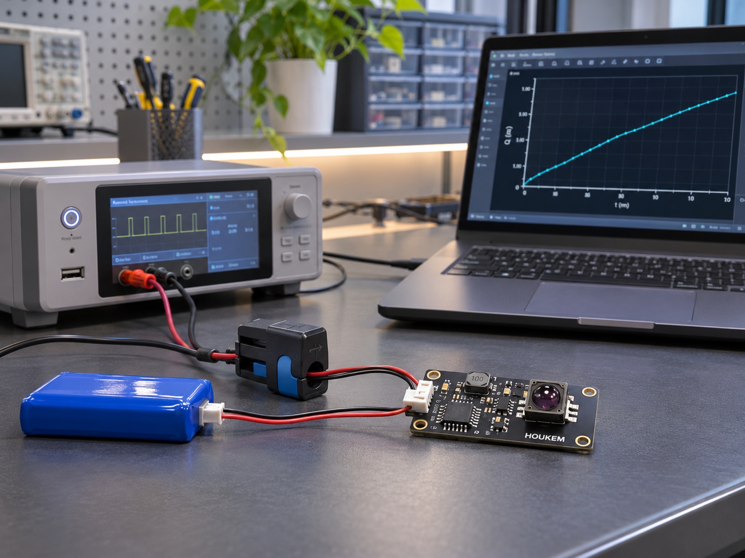
Close the loop with measurement before freezing the design. Run the product from a source that logs charge, exercise the real duty pattern including the worst-case pattern the firmware can produce, and compare delivered charge with the predicted figure over a fixed interval. A difference beyond roughly ten percent usually points to one of four causes: a driver efficiency measured at the wrong operating point, an unaccounted standby load, a capacity derating that does not match the pulse rate, or a pulse shape that differs from the one modelled.
Operational profiles belong in the same test. If the product spends most of its life in a low-rate polling mode and wakes to a dense burst only on detection, the energy budget should be split into those two states and validated separately, since the burst dominates peak current and the polling state dominates total charge. This is where the IR LED energy budget duty cycle becomes a firmware decision as much as an electrical one, and where an average current for pulsed infrared LED figure taken from a datasheet example can mislead.
Specifying the Budget With a Supplier
When the emitter is specified externally, three inputs decide whether a supplier can support the design: the forward voltage band at the intended pulse current, the radiant output expected at that condition, and the thermal limit that applies to the chosen package. Ask for those values against the actual drive condition instead of a generic catalogue number. For a numeric display that shares the same battery, the current accounting method in the 7 segment display current consumption calculation guide uses the same peak-to-average logic on the display side.
Frequently Asked Questions
How do I calculate battery life for a pulsed IR LED?
Multiply the pulse current by the on-time fraction to get average current, then convert it to energy per cycle using the drive voltage. Divide the usable capacity, after derating for rate and temperature, by the energy consumed per unit time.
Which duty cycle should the IR LED energy budget assume?
Use the longest and the most frequent duty profiles the firmware can actually produce, not the nominal one used during development. Budget the worst case for runtime claims and the nominal case for thermal and optical design.
What is a reasonable average current for a pulsed infrared LED in a battery product?
There is no universal figure, because the acceptable average depends on cell capacity, target runtime and the standby load beside it. Set the target from the runtime requirement, then work back to the peak current and duty that fit the optical requirement.
Why does measured runtime fall short of the calculated figure?
Usually the estimate used a nameplate capacity without rate derating, an efficiency measured at the wrong point, or omitted a standby term. It can also happen when the firmware runs a denser pulse pattern in the field than in the bench test.
Does a lower peak current always extend runtime?
No, because the optical requirement then demands longer pulses or more pulses per second. Whether the average falls depends on how the duty profile is rebuilt, so evaluate runtime after the optical requirement is met, not before.
Can HOUKEM supply IR emitters specified for a defined energy budget?
HOUKEM supports IR LED options across a confirmed capability range up to 1900nm for applicable model and project configurations, with custom wavelength and electrical requirements evaluated per project. Share the pulse condition and target runtime, and the engineering team can review the matching emitter options.
Conclusion: Budget Charge, Not Headlines
An IR LED battery energy budget is a chain of four conversions: waveform to average current, average current to energy per cycle, energy per cycle to derated capacity, and derated capacity to operating hours. Each link is cheap to compute and each one is easy to leave out, which is why runtime surprises usually trace back to an omitted link rather than an exotic cell behaviour, and why a battery life calculation for pulsed IR LED products is worth writing down rather than estimating.
Before the design is frozen, put the real duty profile on a charge-logging source and compare it with the model. To review emitter options against your pulse condition, send your project requirements to the HOUKEM team.
IR Receiver Threshold Hysteresis: Stopping False Triggers at the Detection Limit
IR Receiver Sunlight Saturation: Recovering Signal Margin in Bright Conditions