IR Receiver Threshold Hysteresis: Stopping False Triggers at the Detection Limit
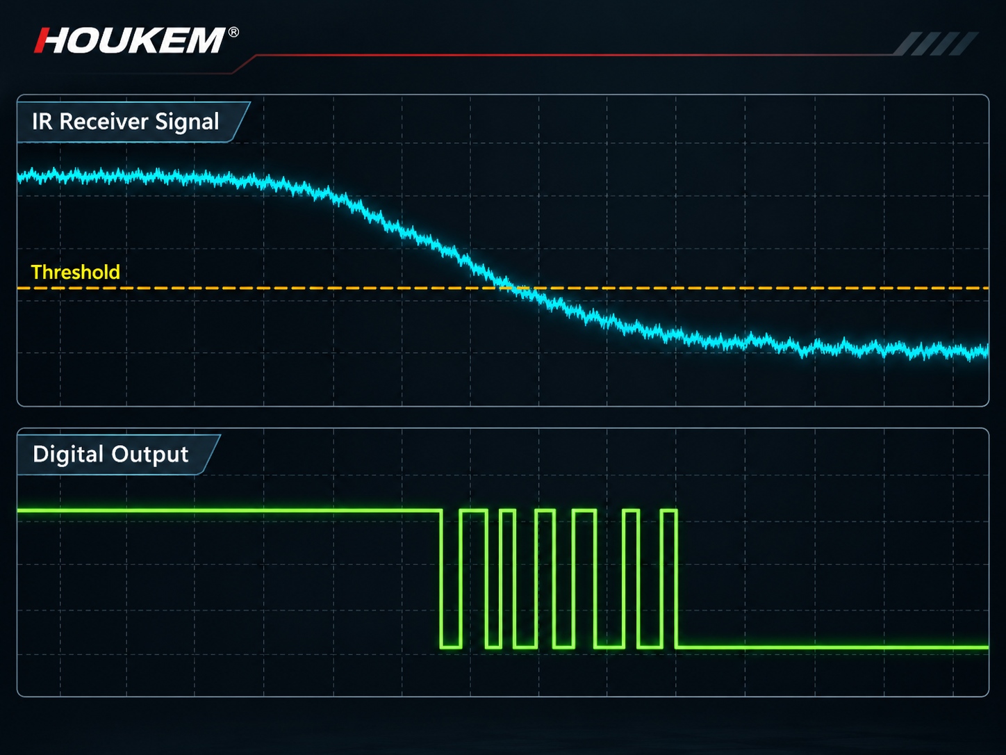
Quick Answer: One Threshold Cannot Hold a Noisy Signal
A single comparison level converts every wiggle that crosses it into an output edge. Hysteresis adds a second level, so the input must fall noticeably below the turn-on point before the output releases. The size of that gap should be set from the measured spread of the received signal, not from habit, and the release direction should be chosen so that a slow-moving or fading return does not re-trigger the circuit.
Why Chatter Appears Near the Limit
As the returned signal approaches the detection threshold, its amplitude and the threshold itself both move. Emitter ageing, supply variation, target surface changes and ambient infrared all shift one side of the comparison, while temperature shift moves the other. When the two sit within the signal's own ripple and noise, the comparator follows that ripple and the output oscillates at whatever rate the noise defines, which is the mechanism behind most infrared false trigger reports once the return hovers near the detection limit.
The symptom is easy to misread. At the far edge of range a photoelectric path may report a stream of short detections instead of one, and a counter downstream will accumulate error without any obvious electrical fault. The working-principle review of how infrared sensors operate is a useful starting point, because it separates the optical, electrical and timing stages that each contribute to this behaviour.
Setting Threshold Margin From Measured Data
Start with data rather than intuition. Log the receiver signal with the target in the near position, in the far position, and absent, at the temperature and lighting extremes the product will meet. The difference between the far-target level and the no-target baseline is the usable separation, and the noise plus drift within each state is the uncertainty. Place the IR detection threshold so that it clears the baseline by more than the uncertainty, which keeps the output from toggling on background alone when infrared detection threshold noise would otherwise decide the output state.
Two quantities should be written down and kept: the received level for the worst acceptable target, and the level for the strongest background the product tolerates. If the difference between them is thin, hysteresis will not create margin that the optical and electrical budget never had.
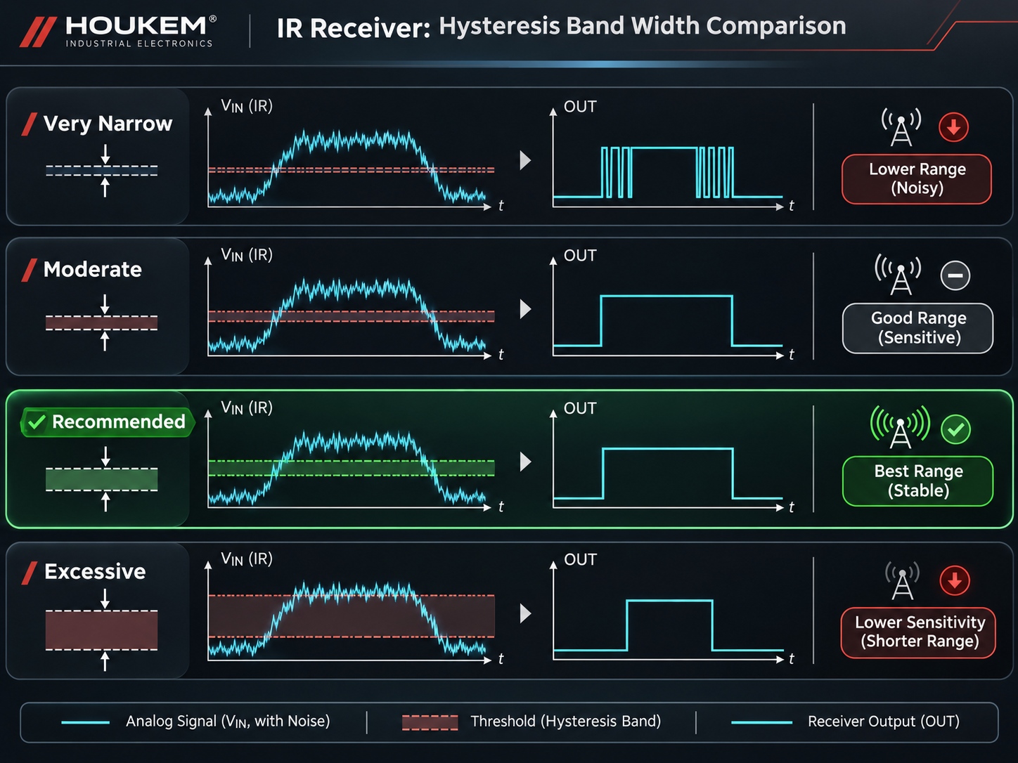
The Hysteresis Band: What It Buys and What It Costs
| Hysteresis width | Effect on false triggers | Effect on real detections |
|---|---|---|
| Very narrow | Chatter near the limit continues; every noise excursion becomes an edge | Fast response, no loss of range |
| Moderate, sized to the noise | Output remains stable across the whole working range | Range essentially unchanged; response still well inside the application's needs |
| Wide | Chatter suppressed, but the release point moves far below the trip point | A slow receding target may hold the output on longer than the product expects |
| Excessive | Background noise no longer retriggers the output | Genuine weak returns can be missed, shortening effective range |
The useful rule is to size the band from the measured noise and drift, then check that the resulting release point still supports the fastest expected target movement. Hysteresis converts sensitivity into stability, and the exchange rate is set by the application.
Ways to Implement the Band
Three approaches cover most products. An analog comparator with positive feedback creates hysteresis with two resistors and no firmware, but the comparator hysteresis band must be recomputed whenever the divider or the reference changes. A receiver with a built-in threshold provides a fixed band, which is convenient until the application needs a different one. A software path samples the receiver, applies a digital threshold pair and a debounce window, which keeps the band adjustable but adds sampling latency and needs care to avoid aliasing fast returns.
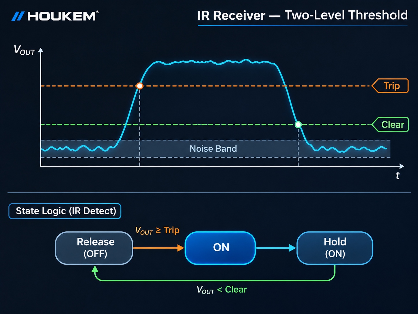
Whichever path is used, the detection state logic should be explicit. The output should carry a flag describing which condition produced the change, because diagnosis later depends on knowing whether a detection was a rise through the trip level or a release through the clear level.
Target Approach and Recede Behaviour
Approach and recede are not symmetric, and the asymmetry is what makes a wide band feel wrong in some products. A target moving quickly towards the sensor crosses the trip level cleanly, while the same target leaving slowly hovers near the clear level for the whole traverse. If the band is too wide, the output stays on after the object has gone; if it is too narrow, the departure produces a burst of edges, and the trip and release levels you set are what decide which of the two the product experiences.
Products that count objects rather than detect presence need a different treatment again: the band should be wide enough to reject chatter between items, and the counting logic should use a time window as well as a level. When unintended emitter leakage is part of the noise, the mechanical and optical remedies in the guide to reducing IR sensor crosstalk are usually more effective than widening the band further.
Validating Across Ambient Conditions
Bench testing at room temperature in a dim room proves very little. The validation should sweep the two variables that move the signal most: ambient infrared and temperature. For each combination, record whether the output is stable at the far target position, whether it releases cleanly when the target is removed, and how long the release takes.
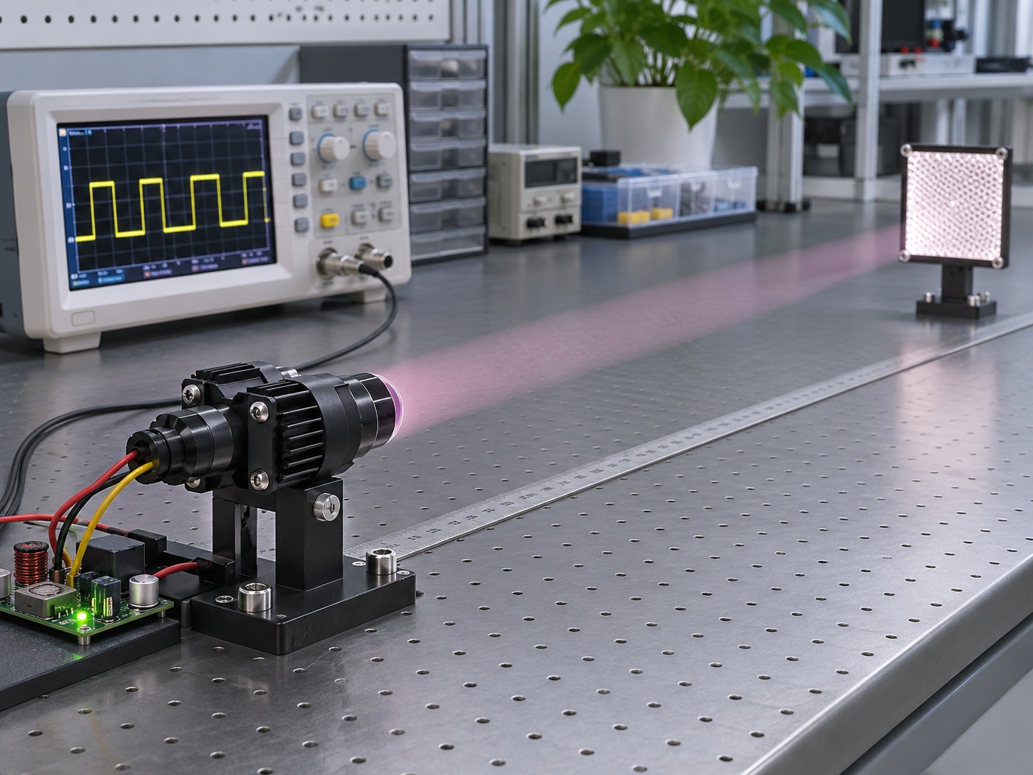
A practical sequence is to test the far position first, then the background-only condition, then the near position, at the coldest and hottest specified temperatures and under strong direct light. If the output is stable at the far position and quiet with no target, the threshold pair is fit for purpose. Emitter choice affects this sweep directly, and the comparison of 940nm and 980nm IR LEDs explains why the longer wavelength often behaves differently under sunlight.
Specifying the Receiver With the Sensor Design
Hysteresis is a property of the whole detection channel, so the emitter, receiver, optics and firmware all need to be specified together. Three inputs to a supplier conversation make that possible: the far-target signal level with its tolerance, the background level at the worst ambient, and the fastest target motion the product must resolve. Any IR sensor hysteresis value you promise should be tied to those three inputs rather than quoted as a standalone number.
Frequently Asked Questions
What is IR sensor false trigger threshold behaviour and why does it happen?
It is a comparison crossing repeatedly because the received signal and the threshold sit within each other's noise and drift. It appears at the edge of range, where the signal has little margin over the background.
How much hysteresis should an IR receiver use?
Enough to cover the measured noise and drift of the received signal, plus a margin for temperature and ageing. Size it from logged data at both signal states rather than from a fixed rule of thumb.
Should hysteresis be implemented in hardware or firmware?
Hardware gives a fast, deterministic band with no sampling delay, which suits high-rate detection. Firmware gives flexibility and easier tuning, but adds latency and needs care to avoid aliasing the receiver output.
Can hysteresis alone fix detection failures in strong ambient light?
No, because a saturated or heavily shifted receiver may not present a usable signal at all. Threshold design only works while the received difference between target and background remains above the noise.
How does target speed interact with the hysteresis band?
A wide band delays the release when a target recedes slowly, while a narrow band produces multiple edges on a fast traverse. Choose the band from the noise, then confirm the timing suits the fastest and slowest motion the product must handle.
Does the emitter choice change the required threshold?
Yes, because wavelength, output and beam width change the received level for a given target and distance. Recheck the threshold pair whenever the emitter or the optics change.
Conclusion: A Gap Sized From Evidence
Threshold hysteresis is a small amount of design work that prevents a large category of field complaints. The band has to be sized from the signal the product really receives, validated at the extremes it will really meet, and revisited whenever any part of the optical chain changes.
When specifying the emitter alongside the detection channel, share the target, distance, ambient condition and required response time with the engineering team. To start that review, send your project requirements to the HOUKEM team.
IR Reflective Sensor Target Reflectivity: Why the Same Sensor Reads Different Surfaces Differently
IR LED Battery Energy Budget: Turning Pulse Current Into Operating Time