IR Reflective Sensor Target Reflectivity: Why the Same Sensor Reads Different Surfaces Differently

Quick Answer: The Return Path Decides, Not the Emitter Output
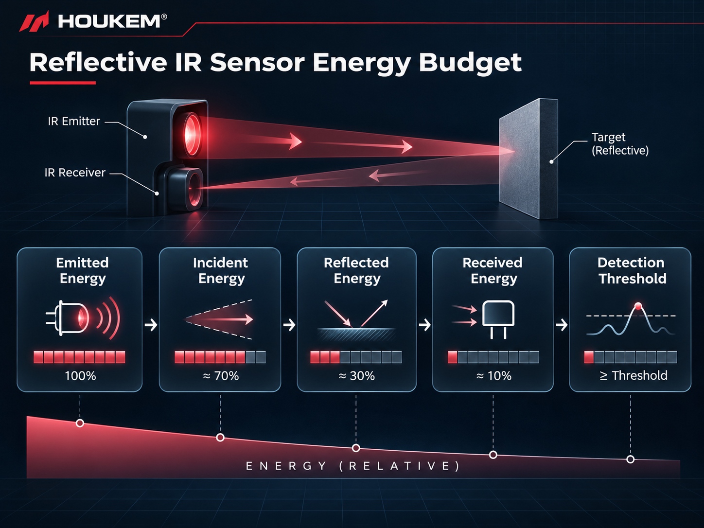
Detection depends on the fraction of emitted energy that reaches the target, reflects back into the receiver aperture and is converted into signal. Surface colour and finish change the first two steps substantially, angle changes the second, and the detector sets the last. The design task is to establish the weakest target the product must detect and confirm that the returned signal still clears the detection threshold with margin at the farthest working distance, which is what an IR target reflectivity study is for.
Diffuse and Specular Reflection Behave Differently
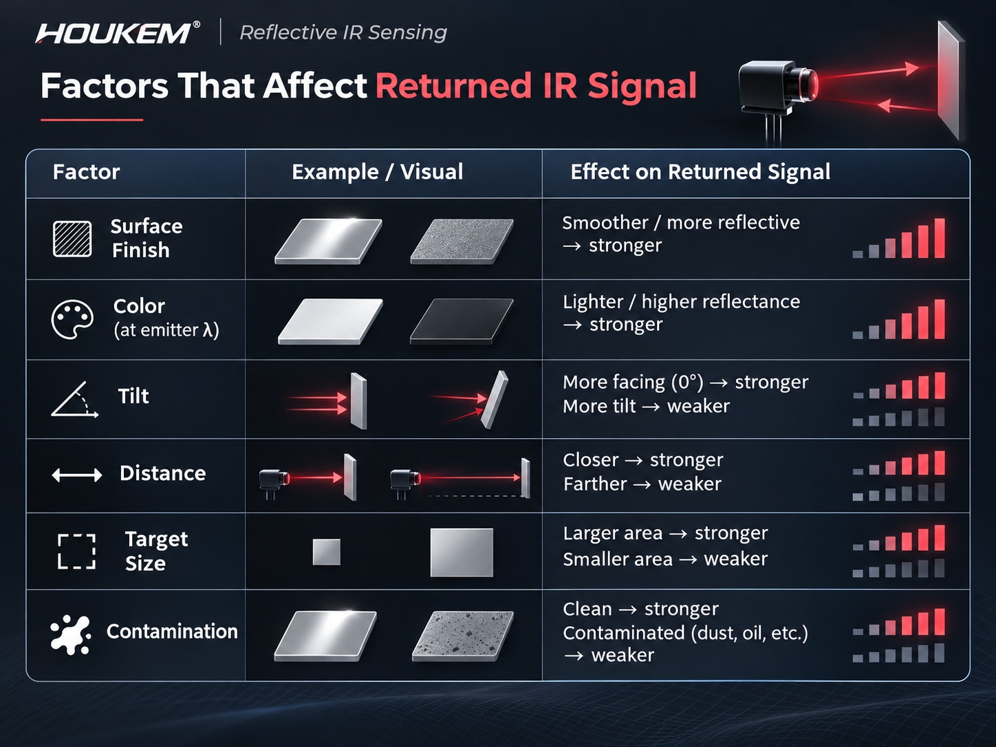
A matte surface scatters the incident beam across a wide range of angles, so a fraction of the energy always returns towards the receiver whatever the mounting angle. A polished or glossy surface behaves more like a mirror: the return is strong but narrowly directed, and it reaches the detector only when the geometry sends it there. This is why a glossy target can produce an excellent signal at one mounting angle and almost nothing at another, and why an IR reflective sensor glossy surface case is the one that most often reaches the service desk.
Curved glossy surfaces add a further complication, because the local surface normal varies across the target and the reflected lobe moves as the object passes. A product that detects a flat painted plate reliably may lose a polished cylindrical part entirely, without any change in distance.
How Colour Changes the Returned Signal
An infrared emitter radiates outside the visible band, so visible colour is a poor predictor of reflectivity at the emitter wavelength. Two paints that look identical to the eye can differ markedly in the near infrared, and a dark visible surface may reflect well while a bright white one absorbs if its pigment behaves differently at that wavelength. Treat the appearance as a hint at best, and measure the return for each candidate surface, because an infrared surface detection task is decided by the return and not by the label on the paint.
Textured surfaces raise another effect: a deep texture traps energy in shadowed pockets at oblique angles, so the return drops faster with angle than it would from a flat sample of the same material. The 850nm versus 940nm IR LED comparison for industrial sensing sets out how emitter wavelength and beam width interact with these surface effects, including how target colour affects IR sensor readings, and the IR LED polar radiation pattern reference explains how the emitted distribution shapes the illuminated patch on the target.
Geometry Multiplies the Surface Effect
Returned energy falls steeply as distance increases, and a small lateral offset between emitter and receiver changes the overlap between the illuminated patch and the receiver's field of view. The same surface therefore produces different signal levels at different mounting distances, which is why a bench test at one distance says little about the product.
| Variable | How it moves the returned signal | What to confirm in the design |
|---|---|---|
| Surface finish | Matte surfaces spread energy; glossy surfaces direct it | The return is acceptable across the mounting tolerance, not only at the nominal angle |
| Surface colour at the emitter wavelength | Absorption varies with pigment, not with visible appearance | The darkest target in the range has been measured |
| Target angle | Oblique surfaces move the reflected lobe away from the receiver | The worst expected tilt still clears the threshold |
| Distance | Return falls with range and with the overlap of illuminated patch and receiver view | The far limit is stated for the weakest target, not the brightest |
| Target size | A target smaller than the illuminated patch returns less than the full-patch figure | Small parts are tested as small parts, not as sheets |
| Contamination | Dust, oil or condensation scatters and absorbs | The effect of a realistic soiled surface is measured, not assumed |
Receiver Response Completes the Chain
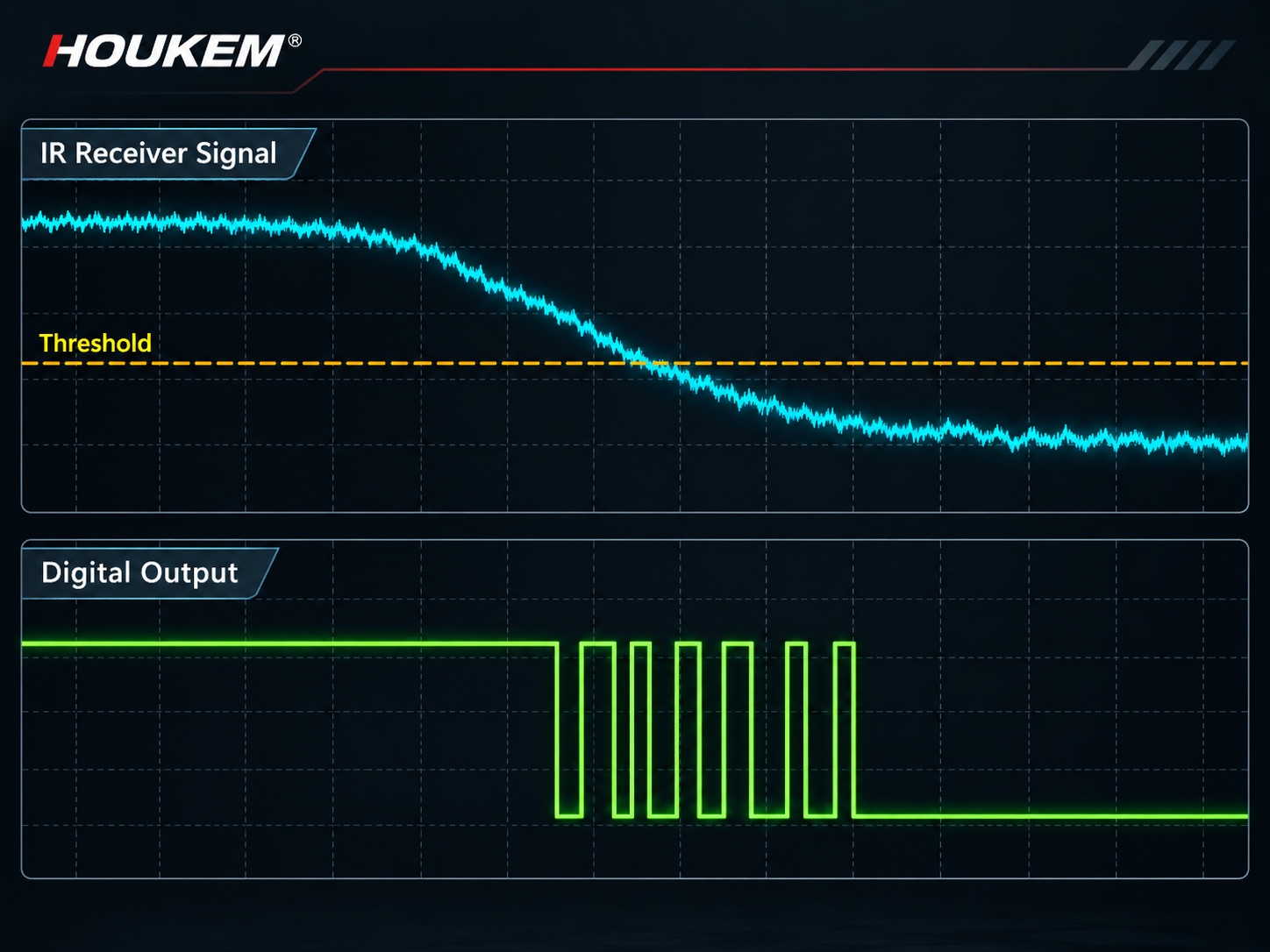
The detector converts the returning energy into current, and its responsivity at the emitter wavelength plus the amplifier gain set the electrical signal the threshold sees. A receiver that is sensitive across a broad band may also respond to ambient infrared that never came from the emitter, which reduces the useful separation even when the target return is adequate. Threshold and hysteresis design for that condition is covered in the guide to reducing IR sensor crosstalk, where unintended leakage paths are separated from genuine returns.
Testing Target Samples Before Tooling
A small sample kit answers most of the questions in an afternoon. Collect the darkest, the glossiest, the most textured and the smallest target in the range, plus one soiled sample of the most likely contaminant. For each, log the receiver output at the near limit, the far limit and the worst angle, and record the values in a table that can be repeated when the target changes.
Repeat the sweep at the temperature extremes and under strong ambient light. A target that passes in a dim room and fails under a window is usually failing on the background side rather than the return side, and the distinction matters because the two have different remedies. This is what an IR sensor target reflectivity testing record should capture, and it is the document to reopen whenever a new part number or finish is introduced.
Design Levers When the Weakest Target Is Marginal
If the weakest target cannot be detected with margin, the options are limited and predictable: shorten the working distance, narrow the emitter beam to concentrate energy on the target, increase the emitted output within the thermal budget, improve the receiver gain, or add optical baffling to keep ambient light out. Each has a cost, and the cheapest is usually to establish the real requirement first, because many products specify a distance that the application never uses.
A common and expensive mistake is to raise emitter current until the bright sample passes, which pushes the emitter towards its thermal limit and can saturate the receiver on the bright target while the dark one still fails.
Writing the Spec So It Survives Production
The specification should name the weakest target, the working distance range, the mounting angle tolerance and the ambient condition, then state the required margin at each. Without those four items a supplier can only guarantee performance against a reference surface, and the production line will discover the spread instead.
The engineering guide to infrared sensor working principles provides the wider context for how emission, reflection and detection fit together, and the guide to IR LED output measurement describes how to characterise the emitter side before the target tests begin, because a measuring setup that reads the emitter wrongly will make every surface look similar.

Frequently Asked Questions
How does target colour affect an IR sensor?
It affects how much energy is absorbed rather than reflected at the emitter wavelength, which is invisible and independent of visible colour. Two paints that look identical can return very different signal levels.
Why does a reflective IR sensor fail on glossy surfaces?
A glossy surface sends the return in a narrow lobe that misses the receiver unless the geometry happens to aim it there. Slight changes in angle or curvature then remove the signal almost completely.
How should IR sensor target reflectivity be tested?
Log the receiver output for each candidate surface at the near limit, the far limit and the worst angle, at the temperature extremes and under strong ambient light. Keep the table as a baseline for future target changes.
Can increasing emitter current solve a weak return?
It raises the returned signal but also increases thermal load and risks saturating the receiver on bright targets. It is a last resort after distance, optics and gain have been reviewed.
Does a darker target always return less infrared?
No, because visible darkness and infrared absorption are different properties. Only measurement at the emitter wavelength gives a reliable answer.
How much margin should be required at the weakest target?
Enough that the return still clears the threshold with the noise and drift the channel sees. Determine the figure from logged data, then confirm it holds at the far limit and at the temperature extremes.
Conclusion: Measure the Weakest Surface First
Reflective sensing is an energy accounting problem in which the surface is one of the largest terms. Establishing the weakest target early, measuring it rather than assuming its behaviour, and specifying the margin at the actual working distance will prevent a design that only works on the sample that happened to be on the bench.
When specifying emitters and optics for a reflective sensing product, share the target samples, working distance, angle tolerance and ambient condition with the engineering team. To start that review, send your project requirements to the HOUKEM team.
IR Receiver Threshold Hysteresis: Stopping False Triggers at the Detection Limit