Decimal Point Brightness Matching: Keeping Small Annunciators in Line With the Digits
Quick Answer: Small Apertures Change the Perceived Brightness
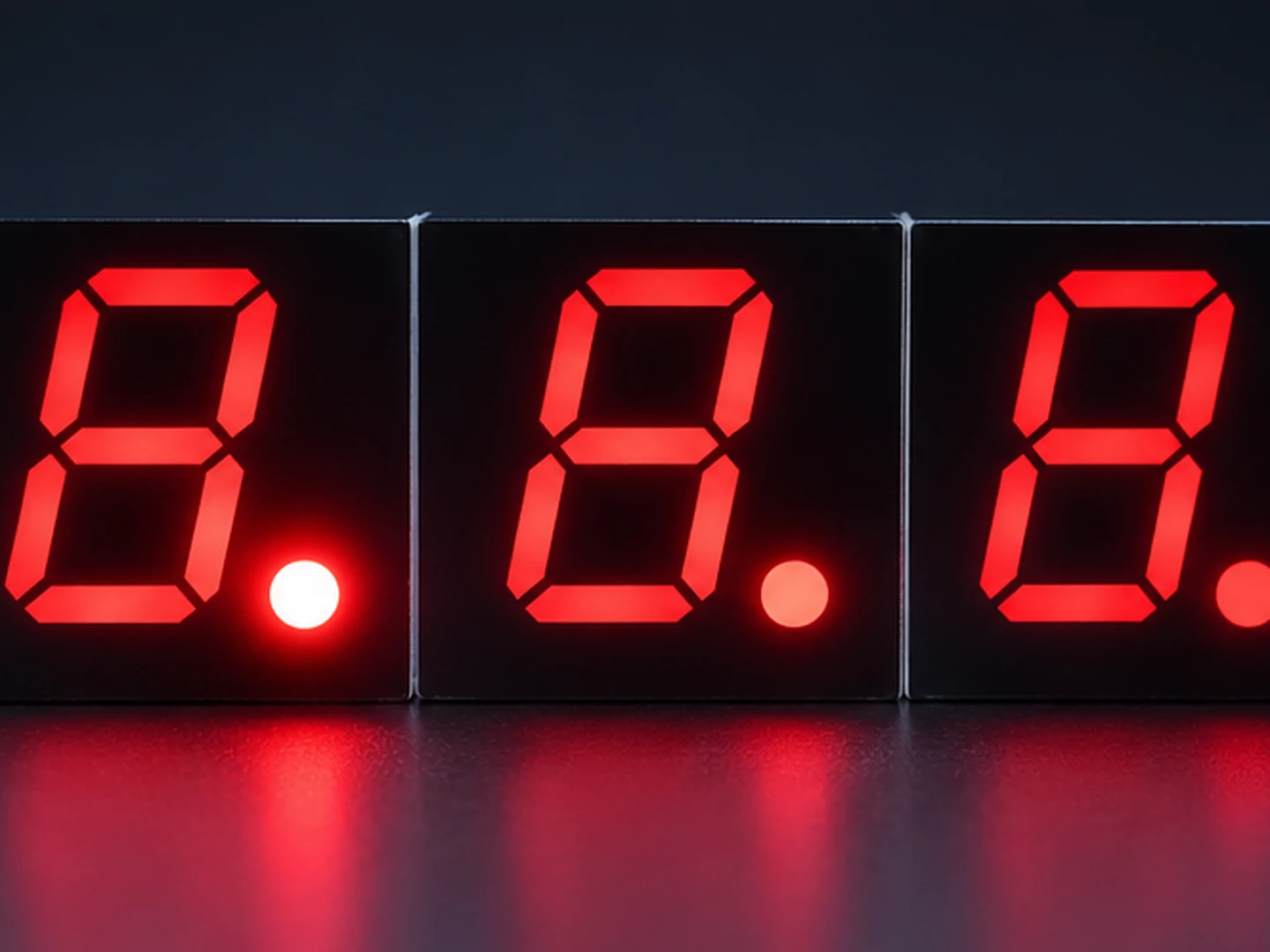
The eye judges a small, bright element differently from a large one at the same luminance, and a decimal point is typically a fraction of a segment's area with a comparable drive current. The mismatch usually comes from three places: the current set for the annunciator, the optical aperture in front of it, and the scan slot it shares. Matching the luminance readings is the starting point, and matching the visual impression is the finish line.
Why a Small Element Reads Different
A decimal point manufactured as a small die in the same package as the digits receives a similar forward current per unit area unless the design changes it. Because its emitting area is smaller, its current density is higher, and at equal current density the luminance can rise, which is the first reason 7 segment decimal point brightness so often needs its own setting. Meanwhile its aperture in the front window is often sized by mechanical clearance rather than by optics, so light escaping from the die edge can leak into the surrounding dark area and make the point look larger and softer than intended, an annunciator aperture design decision that is usually settled by whoever drafts the window first.
The 7 segment decimal point colon wiring guide covers how these elements are connected and counted in the current budget; this article takes the next step and deals with how they look once they are lit.
Current and Resistor Selection for Annunciators
Where the decimal point has its own series resistor or its own driver channel, the numeric display annunciator current can be trimmed directly. Where it shares a channel with a segment, the trim has to come from elsewhere: a different resistor only for that output, a firmware pulse-width adjustment for that digit position, or a supplier-side choice of die for the annunciator. Whichever route is used, the adjustment should be documented on the drawing, because a change made only in firmware does not survive a board revision made by someone else.
Two practical cautions apply. First, lowering the annunciator current also lowers its forward voltage, which changes the drop across the driver and can shift the segment current on a shared channel. Second, a resistor chosen to dim the point at room temperature may dim it less at cold, because forward voltage rises as temperature falls and the current falls with it in a resistor-fed design.
Scan Timing and the Shared Slot
In a multiplexed display the decimal point is usually driven in the same digit slot as the segments beside it, so it receives the same duty cycle. That is convenient but not always correct: if the point appears too bright, the cause may be its higher current density rather than its timing, and changing the scan to compensate will alter the digits as well. The clean order is to fix the current and the aperture first, then confirm that the scan slot is genuinely shared, and only then consider timing adjustments.
| Lever | What it changes | Side effects to watch |
|---|---|---|
| Series resistor or channel current | Directly sets annunciator luminance | Shifts forward voltage and therefore the driver drop on shared channels |
| Firmware pulse width for that element | Adjusts perceived brightness without touching hardware | Disappears if firmware is rewritten; must be documented |
| Window aperture size | Changes how much of the die is visible | Requires a drawing revision and may affect tooling |
| Diffuser or tint in the window | Softens the edge and evens the appearance | Reduces overall transmission, so the digits dim too |
| Die selection at the supplier | Changes luminance at the same current | Must be agreed before tooling; adds a controlled item to the drawing |
| Colour or bin choice | Aligns the annunciator with the digit colour | Binning must be specified per element, not only per lot |
The Aperture and Window Effect
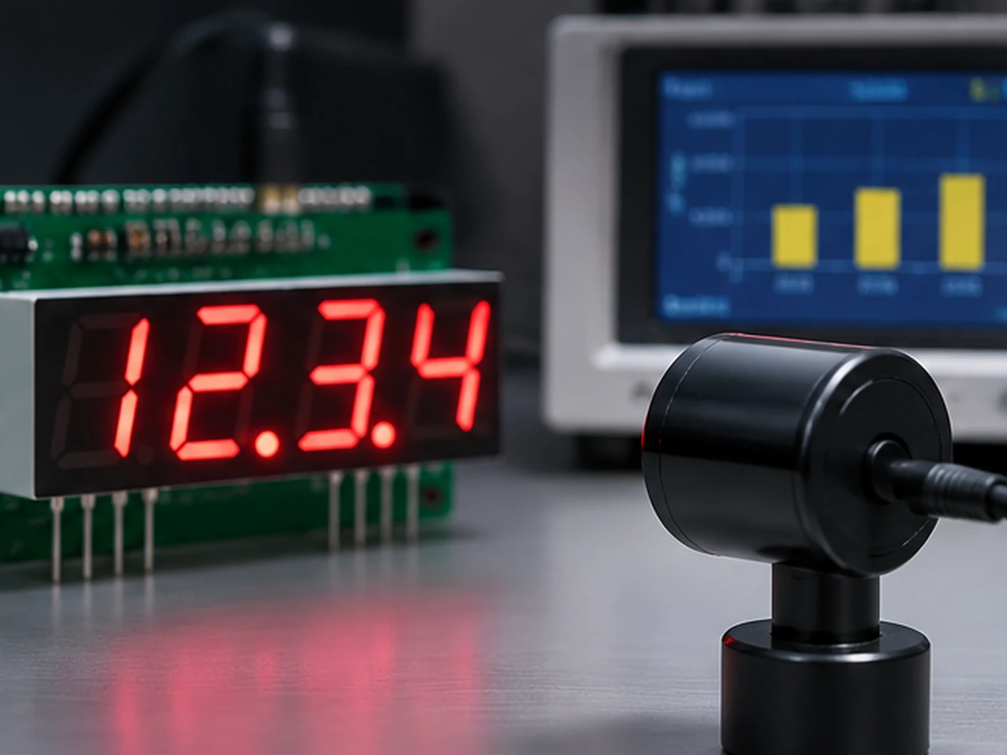
The front window is part of the optical system. A clear window shows the die shape directly, so a small die reads as a hard bright dot; a lightly diffused window spreads the same flux over a larger apparent area, which usually brings it closer to the digits. Tinted windows reduce transmission across the board and can help a display that is too bright in low light, but they do not fix a mismatch between elements, because they attenuate everything equally.
Leakage between the aperture and the segment cavities matters here as well. When light from the annunciator escapes into the dark area beside it, the element looks bloated and the contrast around it falls, which reads as a brightness problem even when the luminance measurement is correct. The custom LED display light leakage analysis describes how to isolate that path with a few readings.
Visual Matching Against Luminance Matching
A luminance meter gives a number, and the number is necessary but not sufficient. Human judgement of a small bright element against a large dimmer one is influenced by size, edge sharpness, background contrast and viewing distance. A practical approach is to set a luminance target for the annunciator relative to the segments, confirm it with a meter, then have several people compare the display at the intended viewing distance under the intended ambient light, because visual versus measured matching do not always agree.
Record both results. The meter reading catches drift in production, while the visual assessment catches the cases where a numerically correct display still looks wrong. Where the display is used in a dark environment, judge it in the dark, because a ratio that reads well under office lighting often looks harsh at night. Any 7 segment colon brightness adjustment should be judged the same way, with the window fitted and the product at its normal viewing distance, since colon LED brightness is judged by the same eye at the same moment.
Writing the Requirement Into the Drawing
The drawing should state the annunciator current separately from the segment current, name the aperture dimension for the decimal point and the colon, and specify the bin or luminance requirement for those elements. It should also state the measurement condition: at what drive current, after what warm-up, and with which window fitted, and how to match decimal point brightness to 7 segment digits once the sample arrives. Display acceptance in general is covered in the LED display brightness uniformity guide, which sets out how to measure position to position without confounding the result with warm-up or angle.
If the display is dimmed in service, repeat the comparison at the lowest operating brightness. Differences that are invisible at full brightness sometimes become obvious at ten percent, because the annunciator and the segments do not dim along the same curve, and small segment current density differences that were tolerable at full drive become visible at the low end.
Where Custom Icons Meet the Same Problem
Status icons, unit markers and separator shapes raise the same question with less established practice, because their area and shape vary widely. The definitions to settle before tooling are set out in the custom segment LED display icons checklist, and the dimming behaviour that governs their appearance at low brightness is described in the guide to 7 segment display PWM dimming.
Frequently Asked Questions
Why does the decimal point look brighter than the digits?
Its emitting area is small while its current is often similar, so current density and therefore luminance can be higher. The aperture and any light escaping from the die edge also make it read as a brighter, softer dot.
Can LED display decimal point current be adjusted separately from the segments?
Yes, where the element has its own resistor or driver channel. On a shared channel the adjustment has to come from the window aperture, the die specification or a firmware pulse-width change.
How do I match the brightness of a 7 segment colon to the digits?
Set a luminance target for the colon relative to the digits, trim the current or the aperture to reach it, then confirm the result visually at the intended viewing distance. Record both the meter reading and the visual judgement.
Does a diffused window fix annunciator brightness mismatches?
It often helps, because it spreads the same flux over a larger apparent area and softens the edge. It also reduces transmission, so the digits dim slightly as well.
Should the matching be checked at dimmed brightness?
Yes, because the annunciator and the segments may not follow the same dimming curve. A ratio that looks correct at full brightness can separate noticeably at the low end.
Can HOUKEM supply a custom annunciator specification with the display?
HOUKEM supports customized LED display projects including decimal points, colons and status icons, with dimensions, current and appearance defined on an approved drawing. Confirm the exact element specification per project before tooling.
Conclusion: Match the Element, Then Match the Eye
Annunciator brightness is decided by current density, aperture and window behaviour rather than by the binning that governs the digits. Setting those three deliberately, documenting them on the drawing and validating at the viewing condition the product will really face keeps a small element from becoming the most noticeable part of the display.
For customized numeric displays with decimal points, colons or status icons, share the element dimensions, target appearance and viewing condition with the engineering team so the drawing can be reviewed before tooling. To start that review, send your project requirements to the HOUKEM team.
7 Segment Driver IC Thermal Dissipation: Estimating the Heat Inside the Chip