


7 Segment Decimal Point Colon Wiring: Planning Extra Segments in a Multi-Digit Display

Quick Answer: Extra Segments Are Still Segments
A decimal point is an additional LED segment attached to the same digit or to a shared position, and a colon is usually a pair of segments driven as one unit. Both follow the same polarity rules as the seven main segments of the digit they belong to.
The wiring question is therefore about placement and sharing rather than about a special component. Once the placement is fixed and the segment count is known, the design checks are the same ones used for the digits.
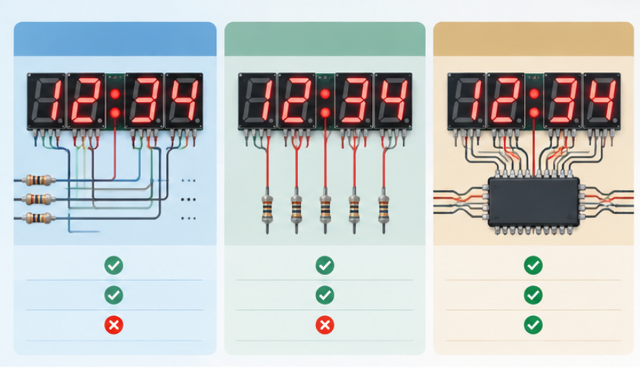
How Decimal Points and Colons Are Wired
In a multiplexed multi-digit display, each digit has a common connection and every segment has its own pin. A decimal point normally shares the segment pin of its digit, so it lights whenever that digit is selected and the decimal point line is driven.
A colon is different because it is not attached to any single digit. In a clock or timer format it usually has its own pair of pins for the two dots, or a single pin when both dots are driven together, and it is scheduled independently of the digit order.
Polarity still governs everything, so the wiring decision has to be made against the anode or cathode arrangement first. Our explanation of common anode versus common cathode wiring sets out how the active level changes which pin is shared and which pin is switched, and that choice propagates into every decimal point and colon connection.
Counting the Segments in the Current Budget
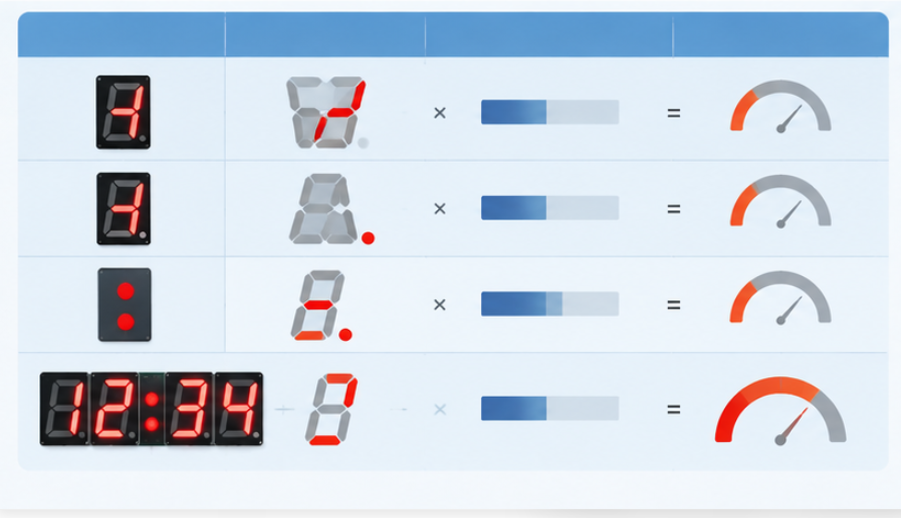
The segment count is easy to underestimate. A four digit display with one decimal point per digit and one colon carries four more driven segments than the digit count alone suggests, and each of those draws the same forward current as a main segment when it is on.
In a multiplexed design the average current depends on how much of the scan period each segment is actually on. A decimal point that is lit continuously still only receives its share of the total on-time, so the budget has to be built from the scan structure rather than from the number of segments alone.
The arithmetic is the same as for a plain digit count, and our walkthrough of the 7 segment display current consumption calculation shows how to include the digit count, the segments per digit and the duty cycle in one figure. Adding the decimal points and the colon to that worksheet is the step that keeps the supply and the driver ratings honest.
Drive Options: Shared Pin, Dedicated Pin or Driver IC
Three approaches cover most designs, and the right one depends on how many extra segments there are and how often they change. The table below compares them against the constraints that usually decide the question.
| Option | How it works | Fits when | Watch for |
|---|---|---|---|
| Shared digit pin | Decimal point shares the segment pin of its digit | One decimal point per digit and no independent control is needed | Cannot be lit separately from its digit |
| Dedicated pin | Extra segments get their own segment pins | The decimal point or colon must be switched independently | Consumes port pins that may be needed elsewhere |
| Driver IC | A dedicated driver scans digits and spare outputs | Several digits plus colons and the host has no spare ports | Spare output count must be confirmed in the pinout |
The shared approach is the most economical and the most common. It fails only when the application needs a decimal point that stays off while its digit is lit, which is rare outside instrument formats with selective decimals.
When the port count becomes the binding constraint, moving to a dedicated driver is usually cleaner than reclaiming pins with extra logic. Our guide to the 7 segment display driver IC covers how output count, scan method and current setting are chosen, and the spare outputs for decimal points and colons belong on that same checklist.
Verification Before Production
Verification should confirm three things on a real sample. The first is that every decimal point and colon lights in the intended position when its digit is selected, which catches a swapped pin before a board is released.
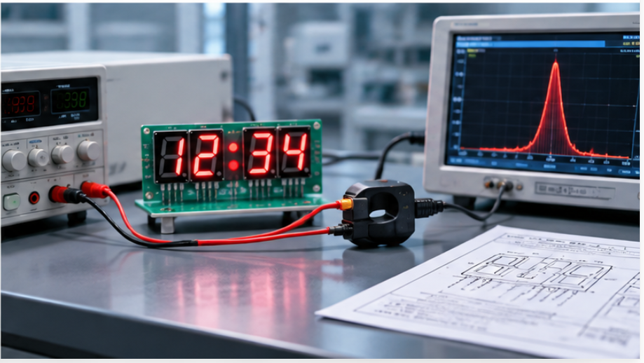
The second is that the total current at the multiplexed duty cycle stays inside the supply and driver limits with all extra segments lit, since that is the worst case rather than the typical one. The third is that brightness across digits, decimal points and colons matches closely enough that the display does not read as uneven.
The same sequence applies whether the display is a standard module or a customized format. The available range and the digit options are catalogued on the 7 segment LED display range page, and a product manager comparing formats can use the same checklist when the enclosure, the digit count and the annunciator layout are still open.
Writing the pin assignment into the drawing before this stage is what keeps 7 segment LED design and multi-digit LED display design reviewable. A later change to one decimal point then becomes a revision rather than a rework.
This is also where 7-Segment Drive & Circuit Design stops being a schematic exercise and becomes a checked decision, because the pin map, the segment count and the scan method all have to agree before the layout is released.
Frequently Asked Questions
How to evaluate 7 segment decimal point colon wiring for an OEM design?
Start from the display format, then record which digit each decimal point belongs to and whether the colon is independent of the digit order. From that map, count the extra segments and check the pin assignment against the available driver outputs.
Which parameters matter most for 7 segment decimal point colon wiring?
The polarity arrangement, the number of independently switched extra segments and the multiplex duty cycle matter most. Together they decide which pin is shared, how much current the budget must carry and whether a dedicated driver is needed.
How does 7 segment decimal point colon wiring affect LED performance?
It affects the current budget and the brightness balance rather than the LED itself, because extra segments add load to the same scan. An underestimated count shows up as dimmer digits or a supply that cannot hold its regulation at full brightness.
How should engineers validate 7 segment decimal point colon wiring before production?
Validate on a sample by lighting every decimal point and colon in its intended position with the digits active. Then measure the total current at the worst-case duty cycle and compare brightness across digits and annunciators.
Can a colon be added to a standard digit module?
Usually a colon requires either an existing annunciator segment in the format or a customized segment layout. Confirm the available positions in the format before assuming a standard module can carry one.
Conclusion: Plan the Extra Segments Early
7 segment decimal point colon wiring is a small part of the schematic that carries an outsized share of the schedule risk. Decide the placement, count the segments into the current budget and confirm the pin assignment while the layout is still flexible.
Once those three items are settled, the display behaves predictably at full brightness and the driver choice stops being a guess. If you are selecting a format with decimal points, colons or other annunciators for an OEM project, send your display requirements to the HOUKEM team and we will confirm the applicable pin and segment arrangement for your design.
7 Segment Display Current Consumption Calculation for Multi-Digit Designs


