Dot Matrix LED Diagnostic Test Pattern: Separating Wiring, Driver and Pixel Faults
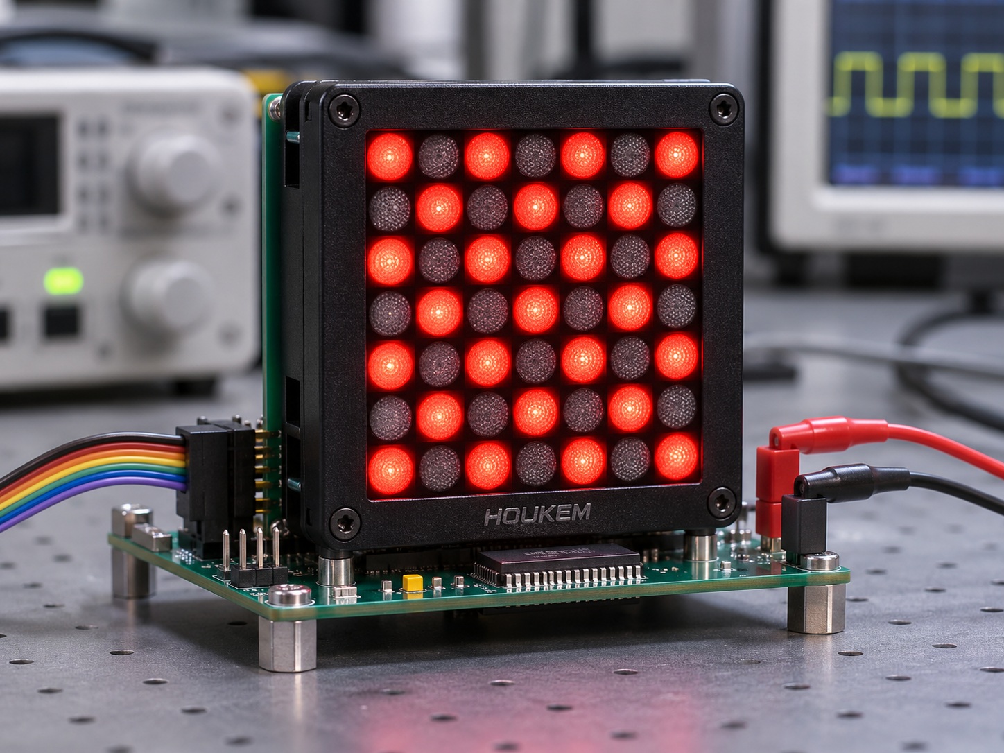
Quick Answer: Random Content Hides Faults, Patterns Reveal Them
Application content lights unpredictable combinations of rows and columns, so a marginal connection can look healthy for hours. Diagnostic patterns light predictable combinations instead, which converts a confusing symptom into a measurable signature. One afternoon of pattern testing routinely saves a wasted PCB spin, because it answers the only question that matters first: which layer is broken.
Why Fault Layer Comes Before Component Swap
A dot matrix display has three layers where faults hide: the row and column wiring between driver and module, the driver channels that sink or source current, and the LED pixels inside the package. Symptoms overlap across layers, so dot matrix troubleshooting by eye alone misleads. A single dead dot could be a failed LED, a broken trace or a stuck driver output, and each has a different fix. The pattern sequence below is designed to separate them in one session, using nothing more than the firmware test mode or a driver test register.
The Pattern Set and What Each One Proves
| Pattern | What It Lights | Signature It Produces |
|---|---|---|
| All-on | Every row and column simultaneously at reduced duty | Weak or missing segments reveal power, ground and common-line problems |
| All-off | Nothing, while the driver stays active | Ghost dots reveal leakage, stuck outputs or PCB contamination |
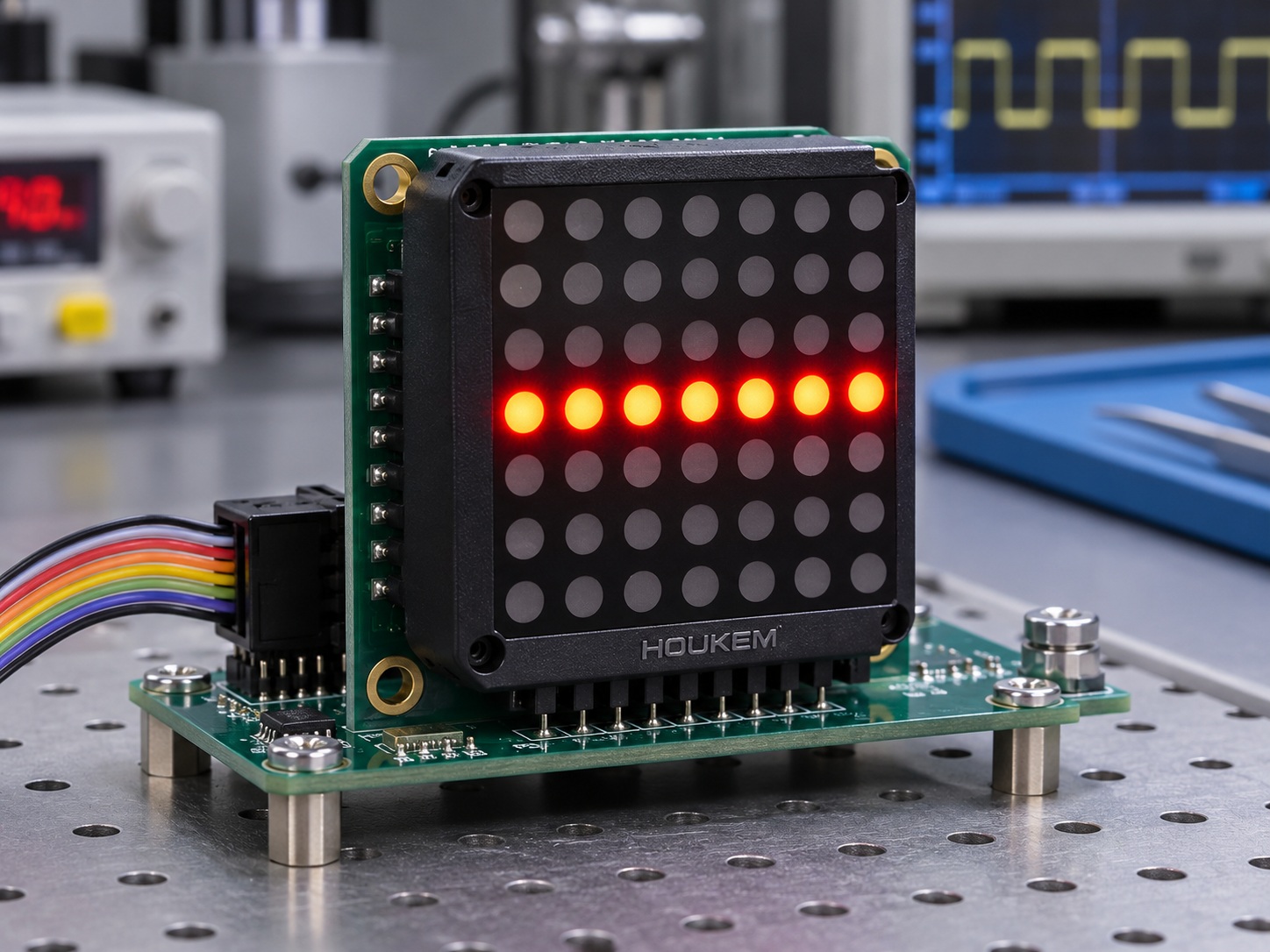
| Walking row | One complete row at a time, in sequence | An entire dark row isolates its row line, connector pin or row driver |
| Walking column | One complete column at a time, in sequence | A dark column points at the column line or column driver channel |
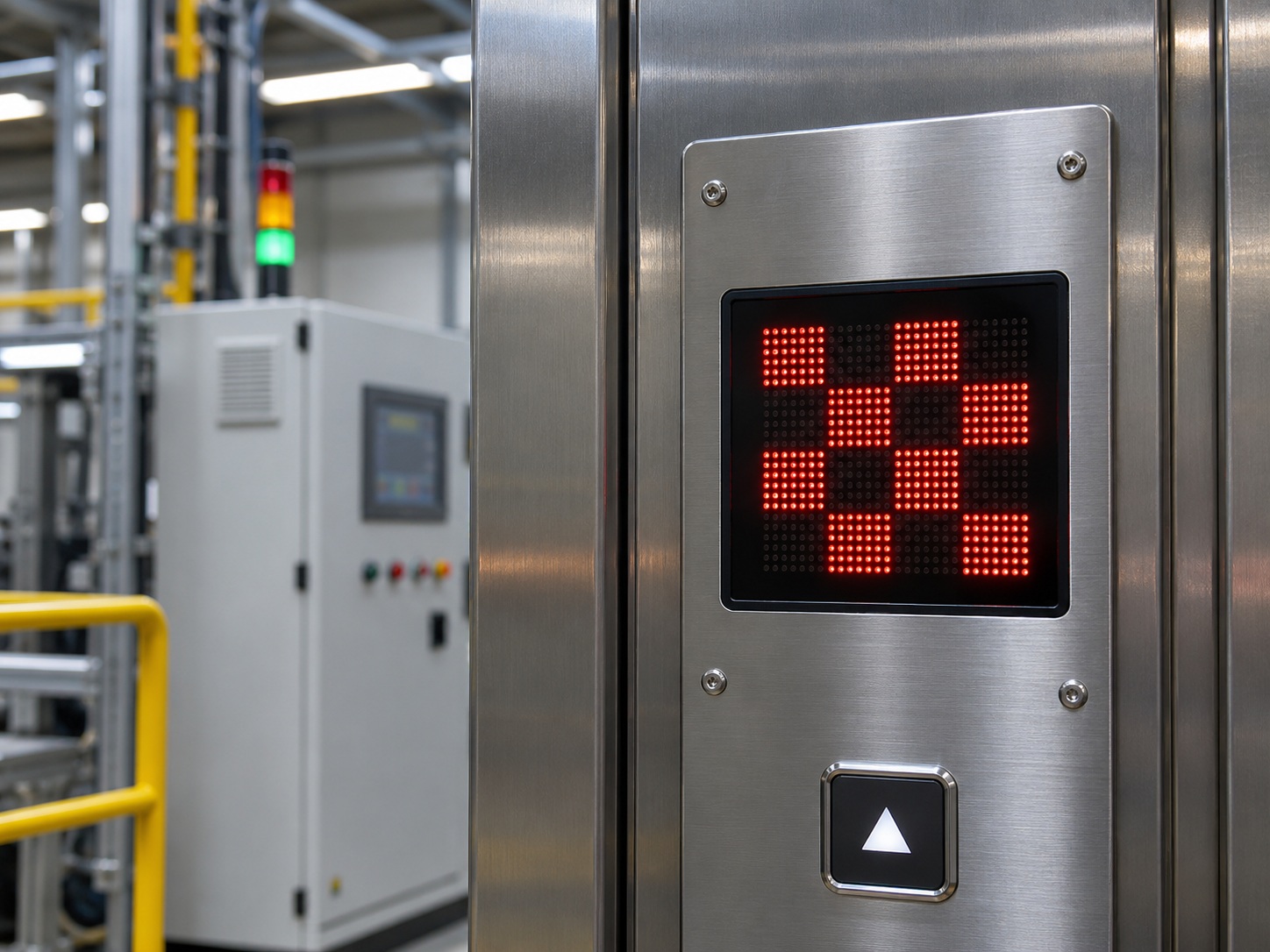
| Checkerboard | Alternating dots in both polarities, then inverted | Crosstalk and adjacency faults appear as lit dots that should be dark |
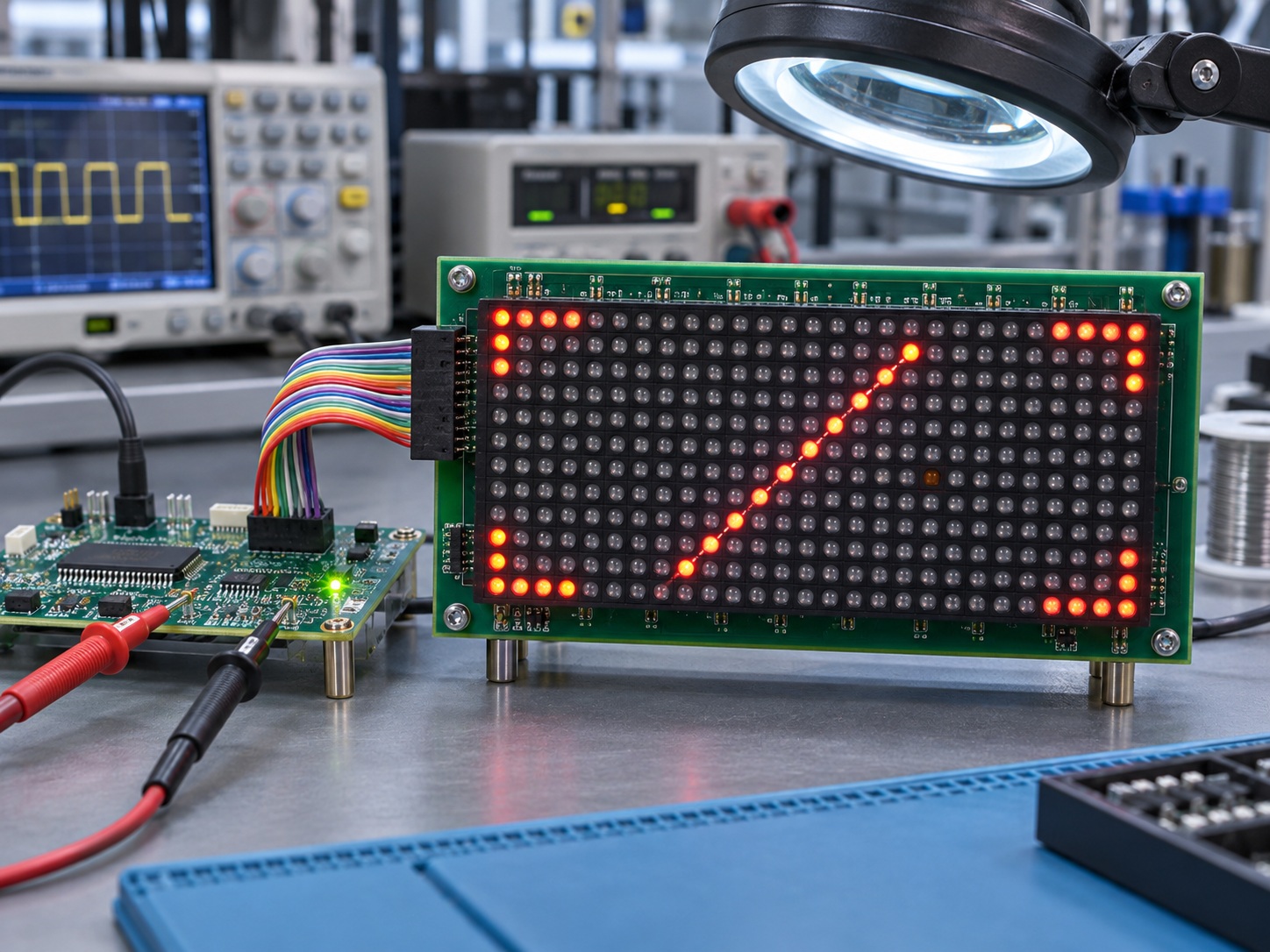
| Single-pixel sweep | One dot at a time across the matrix | Confirms the LED matrix dead pixel test and maps exactly which dots fail |
Run the set in this order. The coarse patterns first, because they fail fast and localise the layer; the single-pixel sweep last, because it is slow and only worth doing once the layer is known. This sequence is the practical form of an LED matrix test pattern method, and it works identically on monochrome, bi-color and RGB dot matrix displays, with color planes tested one at a time.
Interpreting the Signatures
The pattern set pays off at the interpretation step, where each result maps to a specific layer:
- One dark row in the walking row pattern, with all other rows clean, indicts the row line path: connector pin, trace or row driver output. The LEDs themselves are almost certainly fine.
- One dark column in the walking column pattern indicts the column path in the same way.
- A dark dot that appears in the single-pixel sweep but not in the walking tests indicts the individual LED at that coordinate, which is the classic result of an LED matrix dead pixel test.
- Extra lit dots in the checkerboard or all-off pattern indicate crosstalk, leakage or a partially shorted line, often aggravated by board contamination.
- Rows or columns that light weakly only in the all-on pattern point at current capacity or supply droop rather than a broken connection.
When the fault turns out to be a wiring or mapping issue rather than a failed pixel, remember that pin order must still be validated physically before the next board revision. Our guide to pin mapping validation explains that bench procedure, and the PCB assembly tolerance article covers the dimensional issues that can stress connections after assembly.
Building the Patterns into Your Test Mode
Any of these patterns is cheap to implement, and the value compounds when they are built into the product itself. A firmware test mode triggered by a button combination lets field technicians reproduce the same LED matrix walking pixel test the factory used, on the same coordinates, with the same interpretation rules. Keep the pattern definitions and the coordinate naming in one document, so a report that says row 4 is dark means the same thing in Shenzhen and in Ohio. Products with different geometries need only the coordinate map adjusted; the logic of the sequence stays the same whether you are testing a compact 5x7 or 8x8 module or a larger format from the dot matrix display family.
Frequently Asked Questions
How to find bad row in LED matrix quickly?
Display the walking row pattern and photograph the result. A completely dark row isolates the fault to that row line, its connector pin or the row driver, which the single-pixel sweep can then confirm by exclusion.
What does a ghost dot that is never commanded mean?
It usually indicates leakage current from crosstalk, contamination or a partially shorted line rather than a failed LED. Cleaning, checking adjacent line resistance and reviewing drive timing resolve most cases.
Can a driver fault imitate a failed LED?
Yes, because a stuck-off channel looks identical to a dead pixel in application content. The walking patterns separate them, since a channel fault darkens every dot sharing that line while a true pixel fault affects one coordinate only.
Do these patterns work for RGB modules?
Yes, run the full set once per color plane, because the color dies have separate electrical paths. A red-only defect on one coordinate would be invisible in an all-colors pattern.
How does the LED matrix walking pixel test differ from the checkerboard?
The walking test isolates single coordinates, while the checkerboard exercises adjacent dots in alternating states to expose crosstalk and adjacency faults. Use both, because they fail in different places.
Should test patterns run at production duty cycle?
Run the isolation patterns at a reduced duty cycle to protect the display, then repeat the critical rows and columns at production duty for a final check. Marginal drive problems appear only under realistic current.
Conclusion: One Session, One Answer, One Fix
A structured dot matrix LED diagnostic test pattern session replaces guesswork with a layer diagnosis: wiring, driver or pixel. Photograph each pattern, record the coordinates, and only then order parts or cut a board. The discipline costs minutes and routinely saves a revision. If you are specifying dot matrix modules with test-friendly access in mind, our engineering team can discuss driver options and pinout documentation through the inquiry page.