Dot Matrix Pin Mapping Validation: Confirm Rows and Columns Before PCB Release
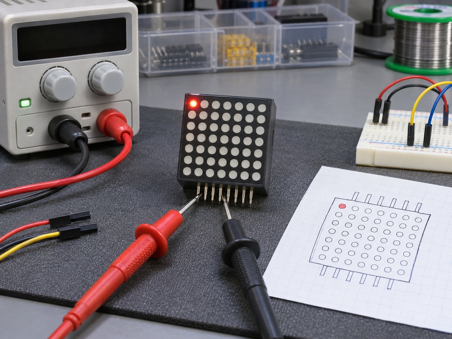
Quick Answer: Trust the Bench, Not the Silkscreen
Datasheets and silkscreens are usually right, but validation exists for the cases when they are not, and for the case when the wrong document revision is on the desk. A one-hour bench check with a current-limited supply identifies every pin, confirms dot matrix polarity and produces a measured coordinate map. That map, not the datasheet photocopy, is what the driver table and the PCB footprint should be built from.
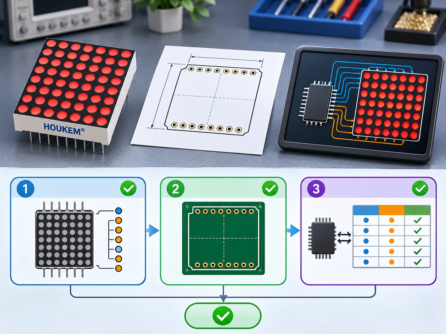
Why Mapping Errors Happen
Matrix modules concentrate several failure sources into one small connector:
- Part families that share outlines but not pinouts, so a module swap looks electrically identical until it does not work
- Revisions that move pins to improve manufacturability without changing the silhouette
- Datasheets borrowed from a different module revision that describe another mapping entirely
- Transcription errors where someone builds the driver table from memory instead of from the measured map
The scanning and drive consequences of getting it wrong are covered in the dot matrix display driver guide; this article stays one step earlier, at the pins themselves.
Reading the Datasheet Map and Polarity
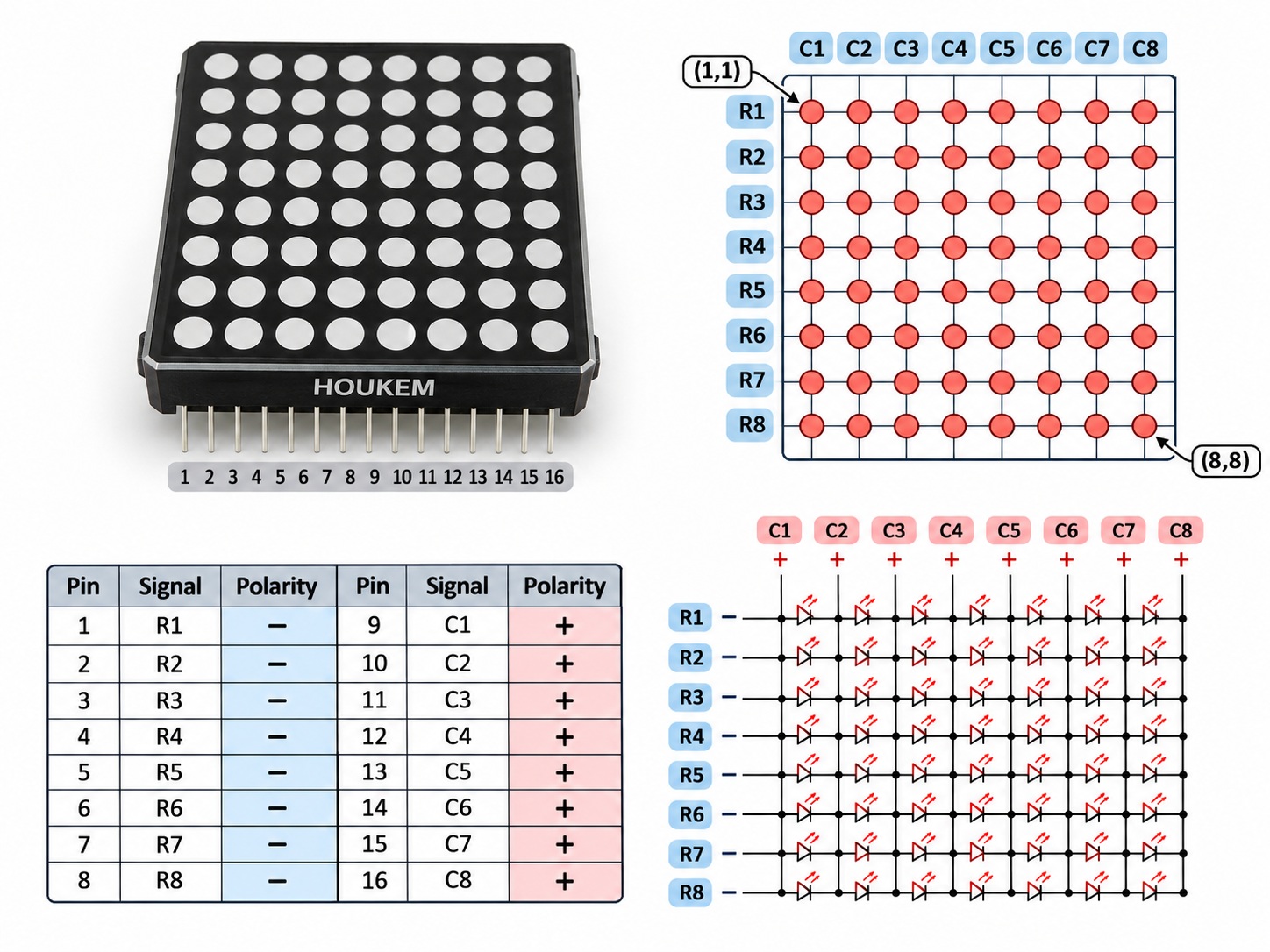
Start by reading the datasheet as a claim to be verified, not as ground truth. Note the stated LED matrix row column mapping, the row and column counts, and whether rows are the anodes or the cathodes. Common-anode and common-cathode modules need opposite drive conventions, and a module bought from a different lot or vendor can silently differ. The general drive topology behind these conventions is explained in the dot matrix display overview; record the claimed dot matrix pinout as hypothesis one, ready to be confirmed or corrected at the bench.
A Bench Check With a Current-Limited Supply
The definitive dot matrix pin mapping test needs only a current-limited supply set to a few milliamps, a resistor, and patience. Put the current limit low enough that a single LED cannot be damaged no matter how it is connected. Then walk the pins: drive one pin high, sweep the others low, and record every pin pair that lights a dot. Rows and columns reveal themselves as repeated patterns across the matrix, and the polarity of each lit pair tells you which side is the anode. Label each physical pin with its measured role as you go, because the working memory of a mapping session is shorter than the session.
Building the Coordinate Map and Driver Table
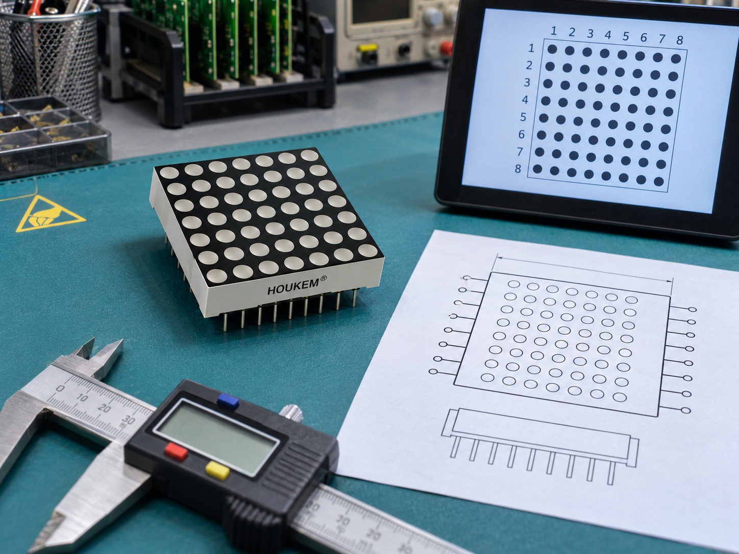
With every pair measured, assemble a coordinate map: a table of physical pins against logical row and column numbers, with polarity marked. This table is the contract between the module and the rest of the design. Derive the driver table from it directly, including any mirrored or rotated ordering that the PCB routing introduces, so firmware never has to "compensate" for the hardware in code. For custom modules, the same map belongs in the drawing package, where the drawing approval process makes it a controlled document rather than a bench note.
Cross-Checking Firmware, Footprint and Sign-Off
Before PCB release, run three cross-checks against the measured map. First, the footprint: pin one position, pitch and row order must match the physical module, a check that sits alongside the coplanarity and pin-fit concerns described in the PCB assembly tolerance guide. Second, the driver table: every row and column must address the coordinate the map says it addresses, verified by walking a test pattern such as a single moving dot. Third, the firmware constants: polarity, scan order and any mirroring must be sourced from the map, not from a previous project. When all three agree with the bench map, how to identify dot matrix row and column pins stops being tribal knowledge and becomes a signed record.
Frequently Asked Questions
How do I identify dot matrix row and column pins safely?
Use a current-limited supply at a few milliamps with a series resistor, drive one pin and sweep the others while recording each lit pair. The current limit protects the module even if you accidentally connect across a single LED without a resistor.
Do common-anode and common-cathode modules ever share a pinout?
Sometimes the physical pin order matches, but the drive polarity is always opposite. Verify polarity at the bench even when the pin positions look identical to the previous module.
Can I skip validation if I use the vendor's driver table?
You can skip it once, and you will still be measuring eventually. The vendor table describes the vendor's module, so confirm that the part in the box is the part on the datasheet before the footprint is committed.
What should the validation record contain?
Record the module part number and date code, the measured pin-to-coordinate map with polarity, and the fixture settings used. A record without the date code cannot be tied to the modules actually delivered.
When should the map be revalidated?
Revalidate whenever the module source, date code or revision changes, and after any long storage period before a new build. Mapping surprises cluster around sourcing changes, not around design changes.
Conclusion: One Measured Map Beats Three Document Revisions
Dot matrix pin mapping validation is cheap, fast and unforgiving of assumptions, which is exactly what a pre-PCB check should be. Verify polarity, measure the mapping, build the driver table and footprint from the measured record, and attach that record to the drawing package. For custom matrix modules supplied with agreed pin maps and validation support, send your module requirements to HOUKEM and the mapping documentation will be part of the approval package.