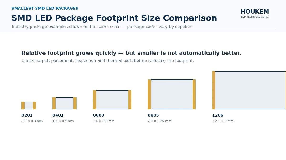
How to Select a Numeric LED Display for an OEM Product

Many display problems only become visible late in development. A module may fit the PCB but sit too far behind the lens. It may look bright during a static bench test but appear dim when multiplexed. A replacement component may have the same external dimensions while using a different polarity or pin layout.
The most effective approach is to treat the display as part of the complete product design from the beginning.
Quick answer: Define what information the product must show, the number of digits required, the normal viewing distance and the available PCB space. Then evaluate digit height, module dimensions, polarity, emitting color, brightness, drive method, package type and operating environment before approving production samples.
Start With the Information the Product Must Display
The application should determine the display—not the other way around.
Before reviewing available models, define exactly what users need to read. Common examples include voltage, current, temperature, time, speed, frequency, production counts, operating modes and error codes.
This first decision affects almost every specification that follows.
A compact timer may require four digits and a colon. A digital meter may need three digits with a decimal point. A temperature controller may also need a minus sign, while a production counter may require five or six positions.
Questions to settle early include:
- What is the highest and lowest value?
- Are decimal points required?
- Is a colon needed for time?
- Must the display show negative values?
- Are unit symbols or status icons required?
- Will leading zeros be displayed or suppressed?
Changing these requirements after PCB layout can affect the module, driver circuit, front-panel opening and firmware. It is therefore worth confirming the complete information format before selecting a part number.
Is a Seven-Segment Display the Right Technology?
A seven-segment module is usually a practical choice when the product primarily displays numbers.
It provides a direct and familiar readout for meters, timers, counters, chargers, appliances and industrial controllers. A multi digit LED display can place several digits in one housing, making alignment and assembly easier than installing separate single-digit components.
Another display technology may be better when the interface must show:
- Full words or long messages
- Detailed icons
- Menus
- Graphs
- Multiple lines of information
In those cases, an LCD, OLED, dot-matrix module or custom segmented display may offer greater flexibility.
The decision should be based on the information being communicated, not simply on which technology looks more modern.
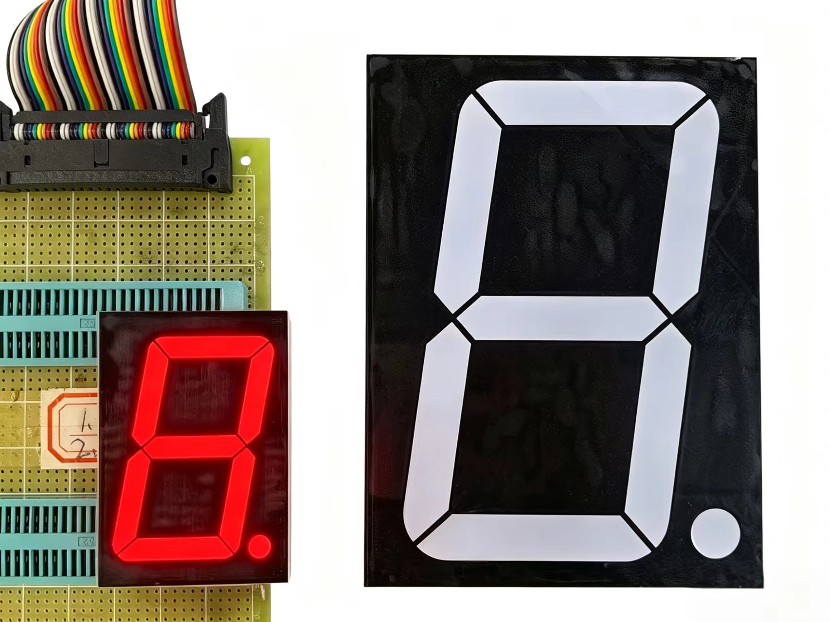
Choose the Correct Number of Digits
Digit count should cover the full operating range without adding unnecessary panel width.
Single-digit modules are useful for mode numbers, status levels and simple error codes. Two- and three-digit displays are common in compact meters and temperature controls. Four-digit modules are widely used for clocks, timers and measurement instruments.
When comparing multi-digit modules, check the actual segment arrangement rather than counting only the visible digit positions. Two four-digit displays may differ in decimal-point locations, colon placement or internal pin connections.
Confirm whether the design requires:
- Decimal points after specific digits
- A central colon
- A minus sign
- Degree or unit symbols
- Additional indicators
- Non-standard spacing
A standard product is preferable when it meets the project requirements. A custom 7 segment display becomes relevant when the product needs unusual symbols, dimensions, pin assignments or optical characteristics.
Match Digit Height to Viewing Conditions
The correct LED display digit height depends on the distance and conditions under which users will read the product.
Smaller characters can work well in handheld instruments and compact panel meters. Larger digits are usually more appropriate for appliances, industrial controllers and equipment viewed from farther away.
Digit height is only one factor in readability. Engineers should also consider:
- Segment width
- Luminous intensity
- Emitting color
- Viewing angle
- Ambient lighting
- Front-lens transmission
- Off-state contrast
- The speed at which users must recognize the value
There is no universal rule stating that a particular digit height is suitable for one exact distance. A high-contrast red display behind a matched filter may be easier to read than a larger but poorly integrated module.
The best way to evaluate LED display viewing distance is to install a sample behind the actual lens and test it under realistic lighting.
Digit Height Is Not the Same as Module Size
A product listed as a 0.4-inch display is describing the visible character height, not the complete component dimensions.
The full footprint also depends on:
- Number of digits
- Housing design
- Digit spacing
- Pin pitch
- Decimal points or colons
- Package type
This difference becomes more important as the digit count increases. A larger four-digit module may affect button placement, enclosure width, connector position and PCB routing.
Review the complete mechanical drawing before reserving board or panel space.
Check the Mechanical Fit Early
Mechanical compatibility should be validated before the PCB and enclosure are finalized.
Important dimensions include the module length, width, height, pin spacing, pin length and distance from the display surface to the PCB. The available front-panel opening must also be checked.
A display can fit the board and still create problems in the assembled product. For example:
- The digits may sit too far behind the lens.
- The housing may contact the front cover.
- Internal ribs may block part of the module.
- The viewing angle may narrow after installation.
- Light may leak between adjacent digits.
- Assembly tolerances may cause misalignment.
The relationship between the display, PCB and front lens should be considered as one mechanical system.
A suitable filter or dark front face can improve contrast and reduce the visibility of unlit segments. Internal partitions may also help prevent light from spreading across neighboring digits.
Do Not Assume Similar Displays Are Interchangeable
Two numeric modules may look almost identical while using different electrical connections.
Differences can include:
- Pin assignment
- Pin pitch
- Common terminals
- Digit-selection pins
- Decimal-point connections
- Internal segment wiring
When qualifying a second source or replacing a discontinued display, compare the new drawing and datasheet against the existing PCB schematic. Matching digit height and housing size is not enough to guarantee compatibility.
Common Anode vs Common Cathode
The choice between common anode vs common cathode is determined by the driver architecture.
In a common-anode display, the LED anodes share a common connection, and individual segments are typically activated through their cathodes. In a common-cathode display, the cathodes share the common connection, and the segments are driven through their anodes.
Neither type is inherently better.
The correct choice depends on:
- The selected driver IC
- MCU output behavior
- Current-sinking capability
- Current-sourcing capability
- Existing circuit design
- Multiplexing method
Polarity should be confirmed before PCB release. Discovering a mismatch after the board is produced may require circuit changes, firmware changes or a different display.
For OEM purchasing, the required configuration should appear clearly on the approved drawing, datasheet and purchase order.
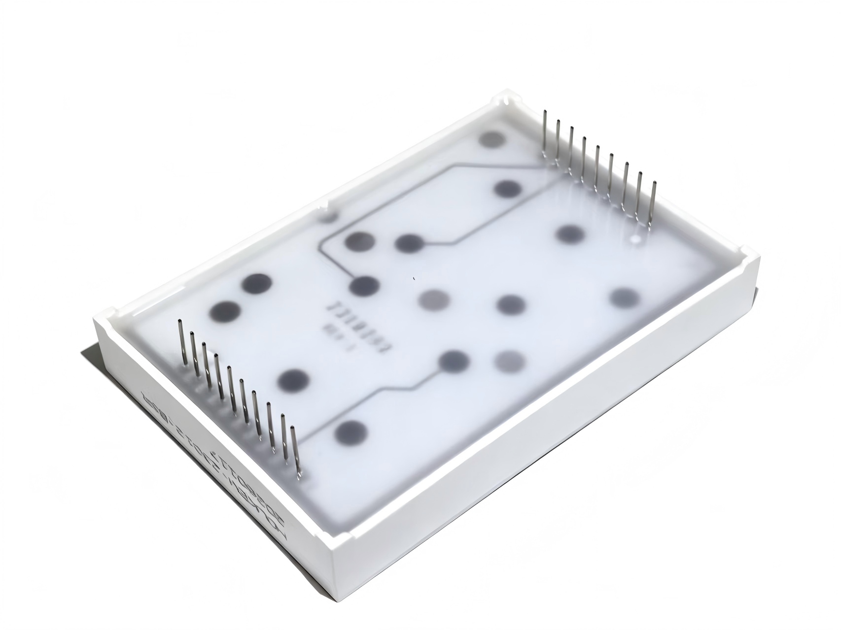
Review Voltage, Current and Drive Conditions
Electrical requirements vary with LED color and internal construction.
Red, amber, green, blue and white segments can have different forward-voltage characteristics. A resistor or driver configuration designed for one color should not automatically be reused for another without checking the datasheet.
Review:
- Typical forward voltage
- Maximum forward voltage
- Recommended operating current
- Maximum continuous current
- Peak pulse current
- Power dissipation
- Temperature derating
Each segment requires appropriate current control. Excessive current may increase heat, shorten service life or create brightness variation.
For products viewed indoors at close range, maximum brightness is rarely necessary. Moderate current combined with a suitable front filter may provide better visual comfort and lower power consumption.
Static Drive or Multiplexing?
The planned drive method has a direct effect on brightness and circuit behavior.
With static driving, each active segment receives continuous current. This approach can provide stable brightness but requires more driver outputs as the number of digits increases.
Multiplexing activates digits sequentially at a high refresh rate. It is widely used in a multi digit LED display because it reduces the number of connections and driver channels.
However, multiplexing introduces several design considerations:
- Duty cycle
- Peak segment current
- Refresh frequency
- Ghosting
- Brightness uniformity
- Timing between digit transitions
- Driver-current capability
A display that looks bright during a direct static test may appear different in the final multiplexed circuit. Sample validation should therefore use the intended driver, duty cycle and firmware timing.
Choose the Emitting Color for the Application
Color selection affects both the appearance and the circuit design.
Red is widely used in measurement and industrial equipment because it provides strong contrast and is easy to recognize. Amber is often selected for warnings, timers and control products. Green may be used for status values or brand-specific designs, while blue and white can create a more contemporary appearance.
The best choice depends on:
- Product branding
- Ambient lighting
- Front-panel color
- Required visual contrast
- Forward-voltage limits
- User expectations
- Whether several colors are used in one interface
Brightness should also be evaluated in context.
A module that appears clear on an open workbench may look dim behind a dark lens. Conversely, an overly bright display can create glare in a dim room.
Test the sample with the actual front-panel material under the lighting expected in normal use.
SMD vs DIP LED Display for OEM Production
The choice between SMD vs DIP LED display should follow the production method and mechanical structure.
When SMD Is More Practical
An SMD display is often a good fit when the product uses:
- Automated reflow assembly
- A low-profile enclosure
- High-density PCB layouts
- Large-volume SMT production
- Minimal manual component insertion
Surface-mounted modules can simplify production when most of the PCB already uses reflow-compatible components.
When DIP Is More Practical
A DIP or through-hole module may be more suitable when:
- The display must stand above surrounding components
- The product requires a specific panel height
- Mechanical board anchoring is important
- The production line uses wave soldering
- An existing PCB already uses through-hole pins
Package selection also affects inspection, rework and alignment. The lowest-profile component is not always the best choice if it cannot sit correctly behind the product window.
Consider the Operating Environment
A display selected for a household appliance may not be suitable for an industrial controller.
The required operating conditions should be defined before supplier approval, including:
- Operating and storage temperature
- Humidity
- Dust exposure
- Vibration
- Daily operating time
- Soldering conditions
- Required product life
The LED module alone does not normally provide waterproof protection. Resistance to moisture and contamination depends on the complete enclosure, lens, gasket and PCB design.
For continuously operating products, thermal conditions and brightness settings deserve particular attention. Driving every segment at the maximum allowable current may not be necessary for reliable readability.
Standard or Custom Numeric LED Display?
A standard numeric LED display is usually the fastest and lowest-risk choice when it meets the project requirements.
Standard models are particularly useful when the product can accept:
- Common digit heights
- Existing pin layouts
- Standard colors
- Normal decimal-point positions
- Established package sizes
They can shorten development time and reduce tooling or minimum-order commitments.
When Does Customization Make Sense?
A custom numeric LED display manufacturer may be needed when the product requires:
- A non-standard module size
- Special pin assignments
- Custom symbols or icons
- Unusual digit spacing
- Multiple LED colors
- A specific face color
- Compatibility with a discontinued component
- A branded front-panel appearance
Before requesting customization, prepare a clear project specification. This should include:
- Required digit count and height
- Overall dimensional limits
- Segment layout
- Emitting color
- Common polarity
- Pin arrangement
- Brightness requirements
- Operating temperature
- Estimated annual volume
- Sample and production schedule
In some cases, an existing display can be modified. In others, new tooling may be required. Providing complete information allows the manufacturer to evaluate both options accurately.
Validate Samples in the Final Product
Sample approval should reflect actual production conditions, not only bench testing.
Mechanical Validation
Install the display on the intended PCB and verify:
- Pin fit
- Module height
- Enclosure clearance
- Window alignment
- Panel opening
- Assembly tolerance
Electrical Validation
Use the final or representative drive circuit to confirm:
- Common polarity
- Forward voltage
- Drive current
- Driver compatibility
- Multiplexing behavior
- Power consumption
Optical Validation
Inspect the display through the production lens under realistic lighting. Check:
- Readability
- Color consistency
- Segment uniformity
- Viewing angle
- Off-state contrast
- Ghosting
- Glare
Production Validation
A pilot build should also confirm compatibility with:
- Reflow or wave soldering
- Cleaning processes
- Automated inspection
- Mechanical assembly
- Aging or reliability testing
A sample that performs well on a development board may still present alignment or soldering problems during mass production.
Specifications to Confirm Before Placing an OEM Order
| Specification | Why it matters |
|---|---|
| Digit height | Determines character visibility |
| Overall dimensions | Confirms PCB and enclosure fit |
| Number of digits | Matches the required value format |
| Pin layout | Determines PCB compatibility |
| Common polarity | Must match the driver circuit |
| Emitting color | Affects appearance and forward voltage |
| Luminous intensity | Influences readability |
| Forward voltage | Required for circuit design |
| Drive current | Affects brightness and power |
| Viewing angle | Influences usability |
| Package type | Determines assembly method |
| Operating temperature | Supports application reliability |
| MOQ | Affects project economics |
| Lead time | Affects production planning |
| Custom tooling | Affects cost and schedule |
These details should remain consistent across the approved drawing, datasheet, sample label and purchase order.
Common Selection Mistakes to Avoid
Several issues appear repeatedly in OEM projects.
Choosing by Digit Height Alone
Digit height does not confirm total module dimensions, mounting depth or pin arrangement.
Confirming Polarity After PCB Design
Common-anode and common-cathode versions require different drive logic. The decision should be made before board release.
Evaluating Brightness Without the Final Lens
A front filter can significantly change brightness, contrast and color appearance.
Testing Under the Wrong Drive Conditions
Static bench testing does not accurately represent a multiplexed production circuit.
Skipping a Pilot Run
Engineering samples may work correctly while production issues appear during soldering, automated inspection or enclosure assembly.
Numeric LED Display Selection Checklist
Before approving a display, confirm the following:
- What values and symbols must be shown?
- How many digits are required?
- What is the normal viewing distance?
- What PCB and front-panel space is available?
- Which digit height provides comfortable readability?
- Does the circuit require common anode or common cathode?
- Which color and brightness suit the application?
- Will the display use static or multiplexed driving?
- Is SMD or DIP more suitable for the production line?
- What operating environment must the component withstand?
- Can a standard product meet the requirements?
- Has the sample been tested in the final enclosure?
Final Recommendation
The best numeric LED display is not necessarily the brightest, smallest or lowest-priced option.
It is the component that fits the product mechanically, matches the driver circuit, remains readable through the final lens and can be assembled consistently at the required volume.
Start by defining the information format and viewing conditions. Then evaluate digit count, module dimensions, polarity, voltage, current, package type and operating environment.
Use a standard display when possible. Consider a custom 7 segment display only when the project requires dimensions, symbols, colors or pin arrangements that standard models cannot provide.
Most importantly, approve the component under the same mechanical, optical and electrical conditions that will be used in production.
Need Help Selecting a Numeric LED Display?
HOUKEM supplies standard and custom numeric LED displays for meters, timers, household appliances, industrial controllers and other OEM electronic products.
Share your required digit count, digit height, overall dimensions, emitting color, polarity, pin layout, operating temperature and estimated annual volume. Our team can recommend a suitable standard model or evaluate a custom solution for your project.
Request a Display Recommendation
FAQs About Selecting a Numeric LED Display
How do I choose the correct numeric LED display size?
Start with the normal viewing distance and available PCB space. Then compare digit height, overall module dimensions, digit count and the required front-panel opening.
What digit height is suitable for my product?
The correct digit height depends on viewing distance, lighting, contrast, front-panel design and available space. Testing samples through the final lens is the most reliable method.
Should I choose common anode or common cathode?
Choose the configuration that matches the MCU, driver IC and current-sourcing or current-sinking architecture. Neither configuration is universally better.
Is SMD or DIP better for OEM production?
SMD is often suitable for automated reflow assembly and compact designs. DIP may be more practical for wave soldering, mechanical support or products that require a specific display height.
When should an OEM use a custom display?
Customization may be necessary when the product requires special dimensions, pin layouts, symbols, digit spacing, colors or compatibility with an existing design.
What should be tested before mass production?
Verify PCB fit, panel alignment, polarity, drive current, forward voltage, brightness, viewing angle, multiplexing performance, soldering compatibility and readability in the final enclosure.
What Is LED Multiplexing in 7 Segment Displays?
How to Reduce Power Consumption in LED Displays: 10 Practical Design Tips for Engineers