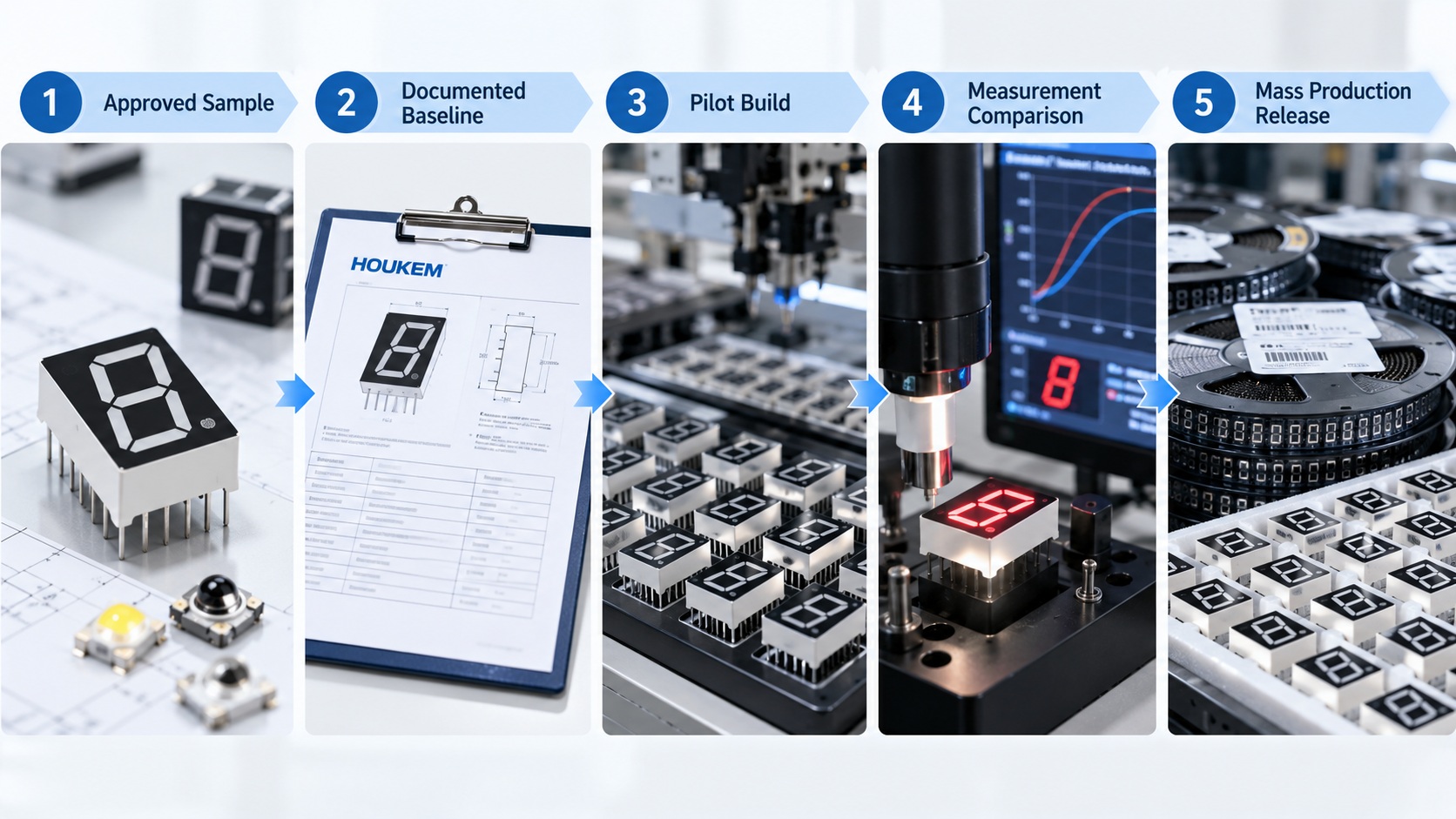
Why LED Display Selection Mistakes Become Expensive

The real problems usually appear later.
A display that looks suitable in a catalog may not fit the PCB. A bright sample may become difficult to read behind a smoked front panel. A part that works during a static bench test may look dim or flicker when driven by the final multiplexing circuit.
These LED display selection mistakes can lead to PCB revisions, delayed product launches, additional sample rounds and inconsistent mass-production results.
A reliable OEM LED display selection process should therefore consider four areas together:
-
Mechanical compatibility
-
Electrical compatibility
-
Optical performance
-
Production requirements
The following ten mistakes are among the most common problems encountered when choosing LED displays for OEM projects.
1. Selecting a Display Based Only on Digit Height
Digit height is useful, but it does not tell you whether a display will physically fit the product.
Two numeric LED displays can both be described as 0.56-inch models while having different package widths, body thicknesses, pin spacing and decimal-point positions. One may fit the enclosure perfectly, while the other may interfere with nearby components or sit incorrectly behind the front window.
Before approving a model, check the complete mechanical drawing, including:
-
Overall package length and width
-
Character height and width
-
Package thickness
-
Pin pitch and pin length
-
Distance between digits
-
Decimal-point position
-
Distance from the package edge to the viewing area
The enclosure also matters. A display may fit the PCB but still appear off-center once it is installed behind the product window.
The safest approach is to review the PCB layout, enclosure drawing and display drawing together rather than approving the part from its digit height alone.

2. Assuming Similar Displays Have the Same Pinout
One of the most costly LED display selection mistakes is assuming that products with the same number of digits and similar dimensions are interchangeable.
There is no universal pin arrangement for every numeric or 7 segment display. Segment pins, common pins and decimal-point connections may differ between manufacturers or even between product series from the same supplier.
A pinout mismatch may require:
-
A new PCB revision
-
Jumper wires on prototypes
-
Firmware remapping
-
Component rotation
-
Delayed sample approval
-
Additional tooling changes
The drawing orientation must also be checked carefully. A front-view diagram and a bottom-view diagram can look similar while representing opposite pin directions.
Before the PCB is finalized, confirm:
-
Pin numbering direction
-
Segment mapping from A to G
-
Common-pin positions
-
Decimal-point connections
-
Pin pitch
-
Drawing perspective
-
Internal circuit diagram
For a custom display, the supplier may be able to match an existing PCB pin layout. This is much easier to arrange before the display structure and tooling are approved.
3. Confusing Common Anode and Common Cathode
A 7 segment LED display is normally designed as either common anode or common cathode.
In a common anode display, the segment anodes share a positive connection, and the required segments are usually activated by pulling their cathodes low.
In a common cathode display, the segment cathodes share a ground connection, and the required segments are activated by driving their anodes high.
The two types may look identical, but they require different control logic and may need different driver circuits.
Choosing the wrong type can affect:
-
MCU logic
-
Transistor arrangement
-
Driver IC compatibility
-
Current direction
-
PCB layout
-
Firmware development
Neither configuration is universally better. The correct choice depends on the existing circuit, driver IC and control strategy.
Do not confirm the display based only on a product photo or an old part number. Request the internal circuit diagram and test the sample with the actual control board before final approval.
4. Comparing Brightness Without Comparing Test Conditions
Brightness values are often presented in millicandela, but a higher number does not automatically mean that one display will look brighter in the finished product.
The measured value may depend on:
-
Forward current
-
LED wavelength
-
Lens material
-
Surface diffusion
-
Viewing angle
-
Static or multiplexed drive
-
Duty cycle
-
Test equipment
-
Ambient temperature
For example, a display measured at 20 mA under static drive should not be compared directly with a display that will operate at a lower average current in a multiplexed circuit.
The front panel can also change the result. A smoked or tinted cover may improve contrast when the display is off, but it can reduce visible brightness when the display is on.
Brightness samples should be tested:
-
At the planned operating current
-
With the intended scan ratio
-
Behind the real front-panel material
-
At the normal viewing distance
-
Under both normal and strong ambient light
-
At the required viewing angles
This gives the engineering team a much more realistic basis for comparison than datasheet brightness alone.
5. Testing with Static DC When the Product Uses Multiplexing
Static bench testing is quick, but it can give a misleading impression of display performance.
In a multiplexed system, each digit is active for only part of the scanning cycle. A four-digit display using a 1:4 scan ratio has a theoretical duty cycle of approximately 25% per digit. A six-digit display may operate closer to 16.7%.
A display that looks bright with one digit powered continuously may appear much dimmer in the final circuit.
Static testing also fails to reveal:
-
Visible flicker
-
Ghosting between digits
-
Uneven digit timing
-
Driver switching limitations
-
Camera banding
-
Pulse-current problems
For meaningful sample evaluation, use the final PCB or an equivalent test board with the intended:
-
Scan ratio
-
Refresh rate
-
Pulse current
-
Driver circuit
-
Supply voltage
-
Dimming method
When requesting samples, tell the supplier whether the product will use static or multiplexed drive. The intended scan conditions may influence the recommended LED chip and brightness level.
6. Choosing Display Color by Name Alone
Color names such as red, green and yellow are not precise enough for many OEM projects.
“Green,” for example, may refer to yellow-green, pure green, emerald green or blue-green. The difference can be obvious when the display is installed next to indicator LEDs, buttons or a branded product interface.
The front window also affects color. A display that looks correct in open air may appear darker or slightly different behind a colored filter.
Instead of relying only on a color name, confirm:
-
Dominant wavelength
-
Peak wavelength
-
Lens color
-
Diffused or transparent surface
-
Front-panel filter color
-
Required on-state brightness
-
Required off-state contrast
For products with several light-emitting components, it is useful to compare all LEDs in the assembled housing. Slight wavelength differences that seem acceptable on separate samples may become distracting when placed side by side.
A physical sample inside the final enclosure is more reliable than a photograph, because camera settings and screens can distort both color and brightness.
7. Choosing SMD or DIP Without Involving Production
SMD and DIP LED displays each have practical advantages. The right choice depends on the product design and the manufacturing process.
SMD displays are commonly selected for:
-
Compact PCB layouts
-
Thin products
-
Automated pick-and-place assembly
-
Reflow soldering
-
High-volume production
DIP displays may be better suited to:
-
Through-hole assembly
-
Larger display packages
-
Stronger mechanical mounting
-
Manual soldering
-
Easier replacement
-
Some industrial applications
A common mistake is choosing SMD because it appears more modern, or choosing DIP because it looks more robust, without checking how the contract manufacturer plans to assemble the board.
The production team should review:
-
Available assembly equipment
-
Reflow or wave-soldering process
-
PCB thickness
-
Placement tolerances
-
Soldering temperature profile
-
Cleaning process
-
Inspection method
-
Repair requirements
Packaging is not only a component decision. It affects assembly cost, production yield, lead time and after-sales service.
8. Ignoring Driver Current and Voltage Drop
An LED display does not work independently from the rest of the circuit. Its real performance depends on the MCU, resistors, transistors, shift registers and driver ICs connected to it.
A display may meet the nominal voltage requirements but still look dim because the driver cannot supply enough current or introduces excessive voltage drop.
Common circuit-related problems include:
-
MCU GPIO current limits
-
Insufficient common-pin current
-
Incorrect resistor values
-
Driver voltage loss
-
Wrong output polarity
-
Slow transistor switching
-
Uneven current between digits
-
Excessive package current
In a multiplexed display, the active common pin may carry the combined current of several illuminated segments. Even when the current through each segment appears acceptable, the total digit current may exceed the rating of the MCU pin or transistor.
Before approving the display, review:
-
Supply voltage
-
LED forward voltage
-
Driver output voltage
-
Peak segment current
-
Average segment current
-
Maximum total digit current
-
Resistor placement
-
Switching speed
-
Power dissipation
A proper 7 segment LED display selection should always be reviewed together with the planned driver circuit.
9. Approving Samples Outside the Final Viewing Environment
A sample that looks clear on an engineer’s desk may become difficult to read once it is installed in the final product.
Viewing conditions can change:
-
Brightness
-
Contrast
-
Color
-
Reflection
-
Viewing angle
-
Apparent character size
-
Camera visibility
An industrial meter may be viewed from above. A household appliance may use a dark front panel. An outdoor controller may need to remain readable in bright daylight. A medical or laboratory product may require comfortable low-light visibility.
Test the display:
-
Behind the real window or filter
-
Inside the final or prototype enclosure
-
At the expected viewing distance
-
At realistic viewing angles
-
Under normal indoor lighting
-
Under strong ambient light
-
At minimum and maximum brightness
-
At the expected temperature range
When the display will be recorded by a camera or read by a machine-vision system, check for rolling bands and flicker under realistic frame-rate and shutter settings.
Final-environment testing often reveals problems that are impossible to see during a standard open-air inspection.
10. Ordering Mass Production Before Freezing the Specification
Some LED display problems are caused less by component performance than by poor version control.
During development, the team may change the color, brightness, pin layout, dimensions or common configuration. If these changes are not recorded in a final controlled specification, the purchase order may be placed against an outdated sample or drawing.
Before mass production, confirm a final specification that includes:
-
Part number
-
Mechanical dimensions
-
Pin assignment
-
Internal circuit
-
Common anode or common cathode
-
LED wavelength
-
Brightness range
-
Forward voltage
-
Test current
-
Packaging type
-
Operating temperature
-
Soldering requirements
-
Inspection standard
-
Approved sample reference
The approved golden sample should match the latest drawing.
For a custom product, tooling, mold, mask or PCB versions should also be recorded. The supplier and customer should be working from the same document revision before bulk production begins.

A Practical LED Display Selection Guide for OEM Teams
Before approving a standard or custom display, work through the following questions.
Mechanical Compatibility
-
Does the full package fit the PCB?
-
Does the viewing area align with the enclosure window?
-
Is the digit height suitable for the viewing distance?
-
Are the decimal points in the correct positions?
-
Does the pin pitch match the board?
Electrical Compatibility
-
Is the display common anode or common cathode?
-
Does the driver support the required polarity?
-
Are forward voltage and current suitable?
-
Can the driver handle the total digit current?
-
Does the pinout match the PCB?
Optical Performance
-
Is the color defined by wavelength?
-
Is brightness measured at a relevant current?
-
Will the display sit behind a filter?
-
Is the viewing angle suitable?
-
Has the sample been tested in real lighting conditions?
Driving Method
-
Will the product use static or multiplexed drive?
-
What scan ratio will be used?
-
What pulse current is planned?
-
Has the sample been tested with the final refresh method?
-
Is ghosting visible during rapid digit changes?
Manufacturing
-
Is the package suitable for the assembly process?
-
Can the factory handle the soldering requirements?
-
Are temperature and time limits documented?
-
Is the component compatible with automated inspection?
Quality and Commercial Requirements
-
Has the final drawing been approved?
-
Is there a signed reference sample?
-
Are inspection criteria clearly defined?
-
Is the part suitable for the expected annual volume?
-
Are customization and tooling requirements confirmed?
This checklist helps turn a general LED display selection guide into a repeatable approval process.
How to Reduce Risk When Choosing LED Displays for OEM Projects
The most effective way to reduce selection risk is to involve the display supplier before the PCB and enclosure designs are frozen.
Provide the supplier with practical project information, such as:
-
Product application
-
Number of digits
-
Character height
-
Available installation space
-
Pin layout
-
Common configuration
-
Display color
-
Target brightness
-
Driving voltage
-
Static or multiplexed operation
-
Scan ratio
-
Viewing environment
-
Operating temperature
-
Estimated annual quantity
For custom projects, it may also help to share the PCB drawing, product window design, current schematic or specification of the existing display.
The purpose is not to send unnecessary documents. It is to make sure the display is evaluated as part of the complete product rather than as an isolated component.
Conclusion
Most LED display selection mistakes happen because the mechanical, electrical, optical and manufacturing requirements are reviewed separately.
A suitable display must fit the enclosure, match the PCB, work with the driver circuit and remain readable under the final viewing conditions. It must also be suitable for the factory’s assembly process and supported by a controlled drawing before mass production begins.
A reliable OEM LED display selection process should confirm the full dimensions, pinout, common type, wavelength, brightness conditions, driving method and production requirements before the part is approved.
HOUKEM supplies standard and custom numeric LED displays, 7 segment displays and related LED display components for OEM applications. Customers can submit their dimensions, pin configuration, color, circuit requirements, driving method and expected order volume for sample evaluation and customization support.
FAQs About LED Display Selection Mistakes
What is the most common mistake when selecting an LED display?
A common mistake is choosing a display based only on digit height. Engineers should also confirm the full package dimensions, pinout, common type, brightness conditions and driving method.
Can displays with the same digit height have different pin layouts?
Yes. Similar-looking displays can use different segment mappings, common-pin positions and decimal-point connections. The complete drawing should be verified before PCB design.
Why does an LED display look dimmer in the finished product?
The final product may use multiplexing, lower current or a tinted front panel. Driver voltage drop, scan ratio and ambient light can also reduce apparent brightness.
Should I choose a common anode or common cathode display?
The choice depends on the MCU, transistor arrangement and driver IC. Neither type is always better, but the selected display must match the circuit and firmware.
When should an OEM project use a custom LED display?
Customization may be appropriate when standard parts cannot meet the required dimensions, pin layout, character arrangement, color, brightness or PCB compatibility.
LED Display MOQ, Pricing and Custom Options Explained
LED Display Lifespan: Key Reliability Factors for OEM Applications