LED Luminous Intensity Measurement Distance: Why Geometry Changes the Number
Quick Answer: Distance Changes the Solid Angle, Not the LED
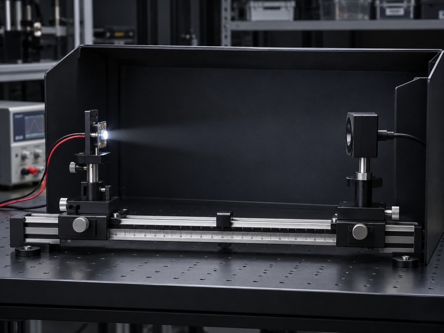
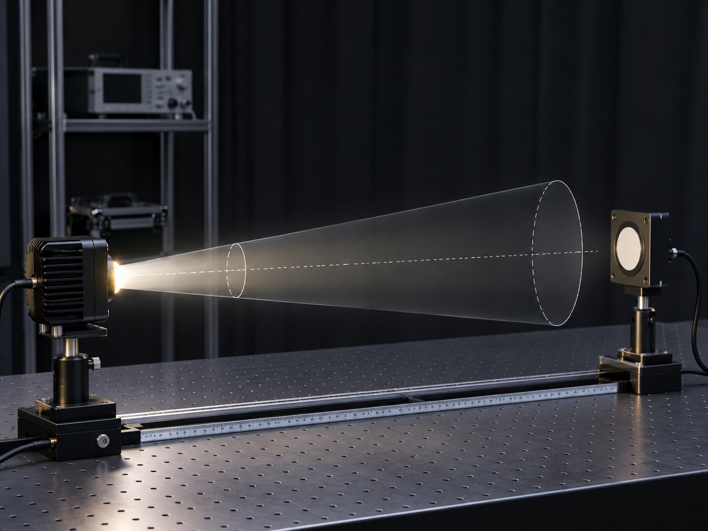
Luminous intensity is luminous flux per unit solid angle, in candela. A detector at the end of a tube or on an optical bench collects flux over some solid angle set by its aperture and the test distance. Move the detector and you change that solid angle, so the reading moves even though the emitter is identical. This is why an LED candela measurement is only meaningful when the geometry is stated and then held fixed.
What the Reading Actually Integrates
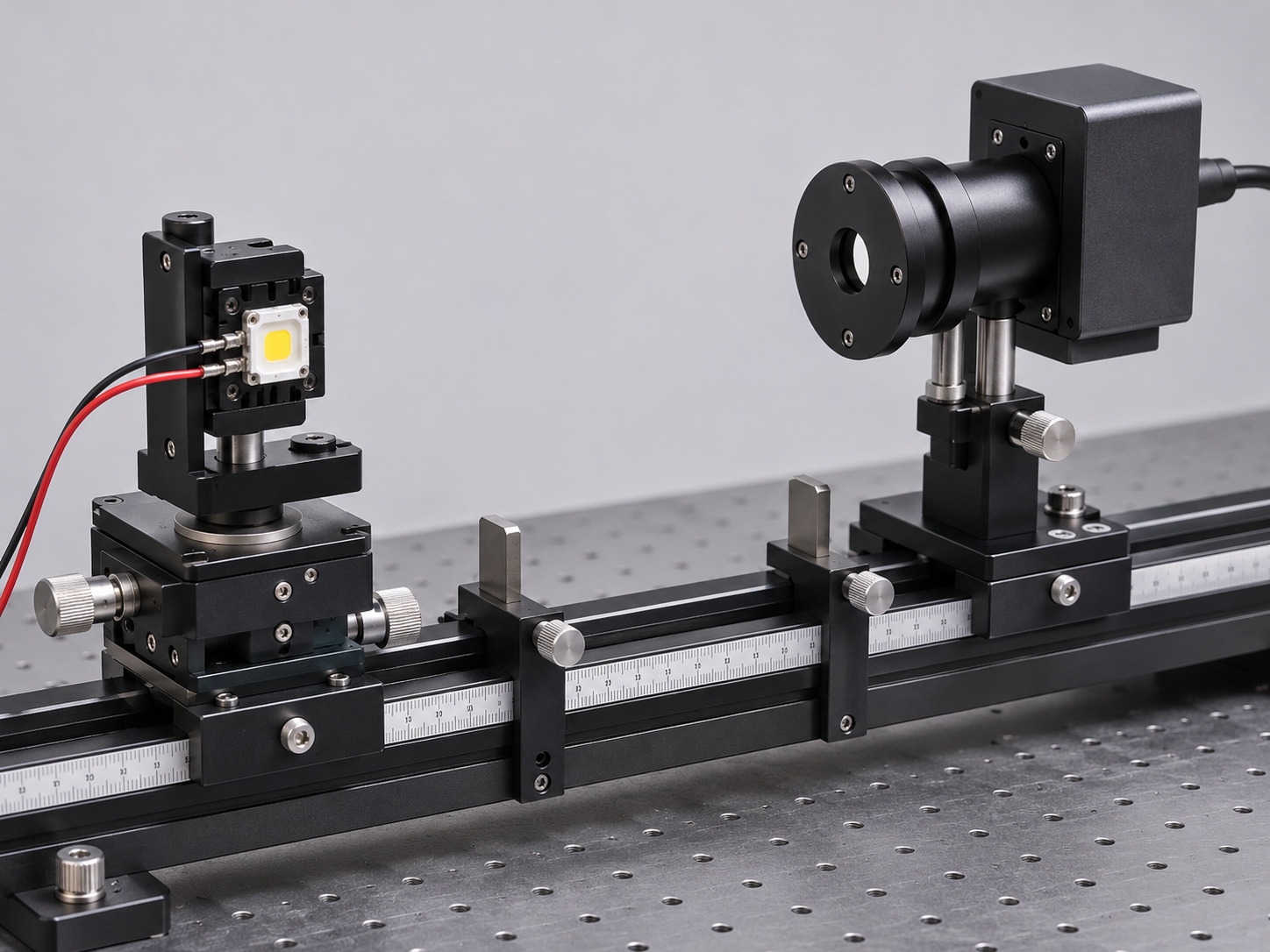
The instrument does not read "the LED's intensity"; it averages the beam over whatever angular range its aperture subtends at the working distance. For a narrow viewing-angle part at short range, a large aperture can clip the beam edge or swallow the whole lobe. For a wide-angle part at long range, the aperture may collect so little flux that noise dominates. The definitions behind these quantities are covered in our comparison of luminous intensity and luminous flux; here the point is narrower: the number on the meter is a geometry-weighted integral, not a fixed property.
Why Test Distance and Alignment Move the Reading
Three effects dominate in practice. First, inverse-square scaling: radiometric and photometric readings fall with distance, and any error in the measured distance becomes a direct error in the inferred intensity. Second, beam shape: the intensity distribution of the LED is not flat, so the sampled angular slice changes with distance. Third, alignment: a small lateral or angular offset of the emitter relative to the optical axis changes which part of the lobe the detector sees. Together they explain why LED intensity readings change with distance by amounts that look like real bin shifts.
Detector Aperture and Near-Field Effects
Close to the emitter, the LED stops behaving like a point source. An aperture that subtends several degrees at 100 mm may subtend a much wider cone at 20 mm, mixing near-field structure into the reading. The far-field convention exists precisely to avoid this: beyond roughly five to ten times the emitting aperture dimension, the angular distribution stabilises. An LED optical test distance inside the near field is not wrong, but results taken there cannot be compared with datasheet values or with other laboratories.
Fixing a Repeatable Bench Geometry
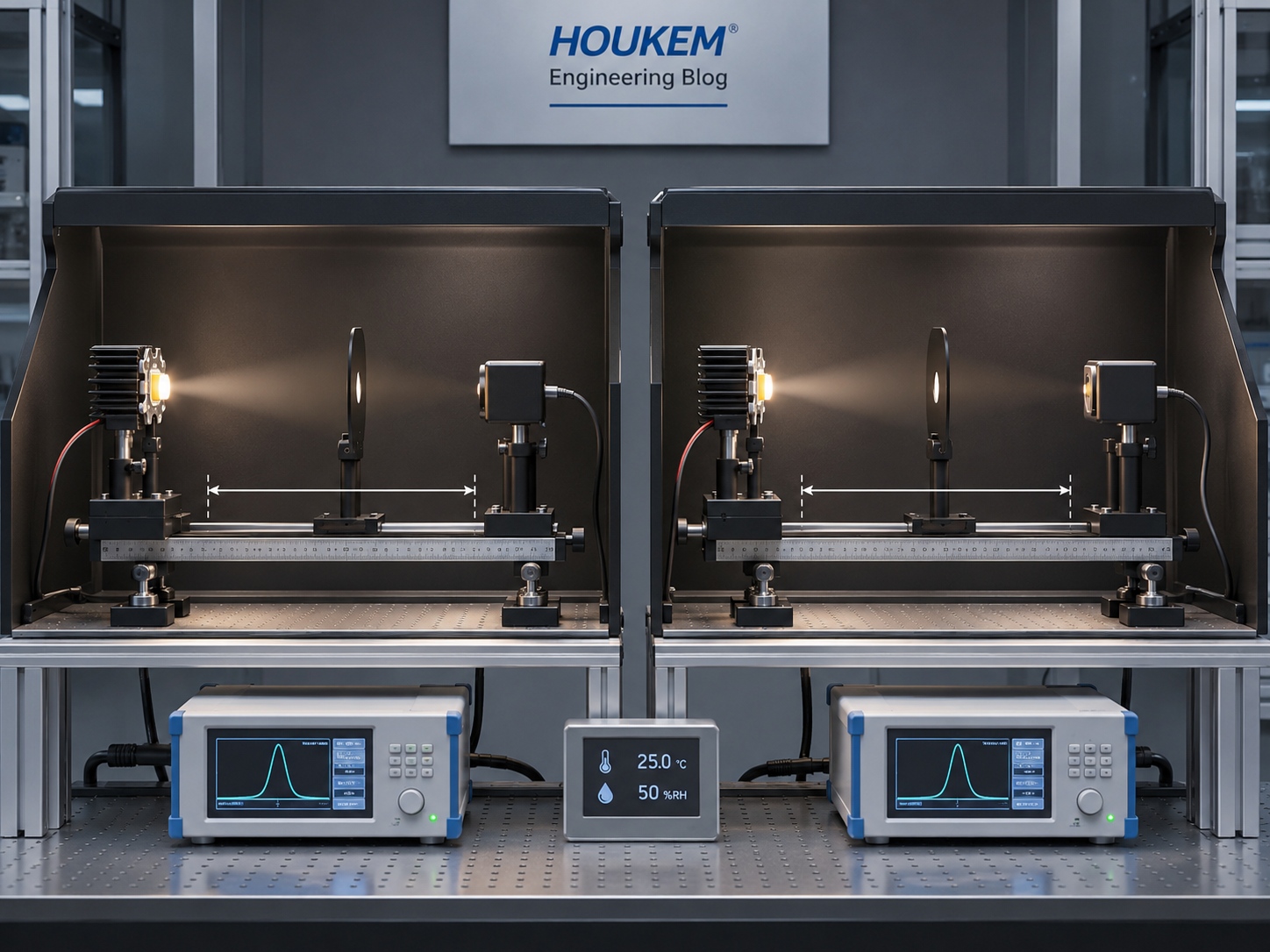
A luminous intensity test is repeatable when the geometry is a controlled parameter, not an accident of the fixture. The table below lists the settings to fix and record before the first sample is measured.
| Geometry parameter | What to fix | Why it matters |
|---|---|---|
| Test distance | One distance in the far field, stated in millimetres | Makes readings comparable across samples and sites |
| Detector aperture | Aperture diameter or acceptance angle, recorded | Defines the solid angle behind every number |
| Alignment | Emitter centred on the optical axis, tilt fixed | Removes lobe-position error from the reading |
| Drive condition | Fixed current and junction temperature | Separates optical geometry from electrical drift |
| Ambient | Controlled light, recorded temperature | Keeps photodetector background stable |
Teams that measure LED luminous intensity this way, how to measure LED luminous intensity becomes a documented procedure rather than a per-engineer habit, and the numbers survive a change of operator.
Comparing Samples and Suppliers Fairly
Supplier comparisons collapse when each side uses its own geometry. Ask for the reporting conditions behind every intensity figure: distance, aperture, drive current and temperature. If a supplier quotes intensity without conditions, request an LED candela test distance and aperture in writing before comparing it with another quote. When the geometry is aligned, remaining differences are usually real: binning, die quality or encapsulation, and those are exactly the differences worth arguing about. The same discipline applies to radiometric work; our guide on photometric and radiometric LED measurement explains how the unit systems map onto each other, and the IR-specific case is developed in how to measure IR LED output.
Frequently Asked Questions
What distance should I use for LED candela measurement?
Use a distance in the far field, typically far enough that the detector aperture subtends a small, stable solid angle, and state it on every report. Consistency matters more than the specific number, because comparisons collapse when the geometry changes.
Why LED intensity readings change with distance is not obvious on my bench?
Because the detector integrates a different angular slice of the beam at every distance, and near-field structure adds further variation inside about five emitter widths. Fixing one distance and one aperture removes most of the drift between readings.
Can I compare my bench result with the datasheet value directly?
Only if your distance, aperture and drive condition match the datasheet reporting conditions. Otherwise convert nothing and re-measure under the datasheet geometry, or ask the supplier for the missing conditions.
Does detector aperture size matter if distance is fixed?
Yes, because the aperture sets the solid angle that every reading integrates. Two benches at the same distance but different apertures will legitimately disagree, especially on narrow-beam parts.
How should intensity results be reported between supplier and buyer?
Report the candela value together with test distance, aperture, drive current and temperature, so the reading can be reproduced. A number without its geometry is not transferable evidence.
Conclusion: Fix the Geometry, Then Argue About the LED
Most intensity disputes are geometry disputes in disguise. Fix the distance, aperture, alignment and drive condition, record them with every result, and the LED luminous intensity measurement distance stops being a source of noise and starts being a shared standard. If you need displays or LEDs supplied with measurement conditions stated on the specification, send your reporting-geometry requirements to HOUKEM and they will be written into the project documentation before sampling.